


 Here’s a digital frequency comparator for oscillators that indicates the result through a 7-segment display and a light-emitting diode (LED). When the frequency count of an oscillator is below ‘8,’ the corresponding LED remains turned off. As soon as the count reaches ‘8,’ the LED turns on and the 7-segment display shows ‘8.’
Digital Frequency Comparator Circuit
This demo circuit uses two NE555 timers configured as astable free-running oscillators, whose frequencies are to be compared.
The circuit of the digital frequency comparator portion comprises two 74LS90 decade counter ICs (IC2 and IC6), two 74LS47 7-segment display driver ICs (IC3 and IC7), 74LS74 set/reset flip-flop (IC4), 74LS00 NAND gate (IC8) and two 7-segment displays (DIS1 and DIS2). The astable free-running oscillators built around the timers are the frequency sources for the corresponding counters.

Circuit operation
When power supply to the circuit is switched on, timing capacitor C1 starts charging through resistor R1 and potmeter VR1. As the capacitor voltage reaches 2/3Vcc, the internal comparator of IC1 triggers the flip-flop and the capacitor starts discharging towards ground though VR1. When the capacitor voltage reaches 1/3Vcc, the lower comparator of IC1 is triggered and the capacitor starts charging again. The charge-discharge cycle repeats. That means, the capacitor charges and discharges periodically between two-third and one-third of the power supply (Vcc). The output of NE555 is high during charging and low during discharging of capacitor C1.
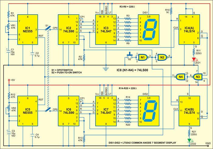
The other oscillator (IC5) works similarly. The oscillator frequency can be varied by the potentiometer (VR1 or VR2). Output pins (pin 3) of the oscillators (IC1 and IC5) are connected to the respective decade counters (IC2 and IC6) through the DPDT switch.

IC2 and IC6 count the initial eight cycles. IC 74LS90 is a 4-bit ripple decade counter. It consists of a divide-by-two section and a divide-by-five section counter. Each section has a separate clock input. The input of the divide-by-five section (CP1) is externally connected to the P output (pin 12) of the divide-by-two section (CP0). When the divide-by-two section receives clock pulse, it becomes a divide-by-ten counter.
Decade counter 74LS90 is reset by a high pulse at its pins 2 and 3. Initially, pins 2 and 3 are pulled down by resistor R2. The P through S outputs of IC2 are connected to the A through D inputs of IC3. Pin 11 (S) of IC2 is also connected to pin 3 of IC4(A) for providing the clock pulse. The count is displayed on the 7-segment display.
Display
The 7-segment decoder/driver (74LS47) accepts four binary-coded decimals (8421), generates their complements internally and decodes the data with seven AND/OR gates having the open-collector output to drive the display segments directly. Each segment-driver output is capable of sinking 40mA current in the ‘on’ state. Pins 3, 4 and 5 of the display driver are connected to Vcc to disable the ripple-blanking input (RBI), blanking input (BI)/ripple-blanking output (RBO) and lamp test (LT).
IC3 provides segment data to the 7-segment display through current-limiting resistors R3 through R9 (each 220 ohms).
IC 74LS74 (IC4) controls the reset pin (RST) of NE555. It is a dual D-type flip-flop with direct clear and set inputs and complementary outputs. The input data is transferred to the outputs on the positive edge of the clock pulse. Since the Q output is connected to the data input D, the flip-flops work in toggle mode.
Circuit application
Initially, reset pins 1 and 13 of the flip-flops are pulled high via resistor R10. When the reset pin of any flip-flop receives a low pulse from NAND gate N2 of IC8, the flip-flop is reset and its Q output goes high. On receiving a clock pulse, the Q and Q outputs of the flip-flop go high and low, respectively, and the LED turns on. The low output of IC4 resets the oscillators. The reset signal is derived with the help of NAND gates N3 and N4.
When switch S2 is pressed, both the oscillators and the respective counters start working. As soon as any of the counters counts ‘8,’ the corresponding display shows ‘8’ and LED glows. This means that oscillator has a higher frequency. Now both the counters stop counting because the flip-flop output goes low to reset both the astable oscillators.
In case the frequencies of both the astable oscillators are same, both the displays show ‘8’ and LED1 and LED2 glow at the same time.
The article was first published in February 2005 and has recently been updated.