DALI (Digitally Addressable Lighting Interface) is a young and intelligent choice to control modern lighting systems in homes and offices. It is an international standard which allows two-way digital communication for the control of one or more lighting devices (e.g. electronic ballasts, dimmers, LED drivers, emergency lights and exit signs). A user can send a command or message to a ballast. The ballast with that address picks it up and follows the instruction. You can not only switch the lights on and off, but also pick the color and brightness you want. A message would be “Dim up all lamps for 200 ms” or “Set lamp 3 to 100% light level”.
While one controller or master can monitor and control 64 lighting devices or slaves with interfaces, the protocol also allows several DALI controllers to be linked together. This can let you scale your lighting system from a room, to a floor, to a building and beyond.
Want to know more how to implement lighting automation with this young tech? Here are some reference designs which demonstrate lighting control applications with DALI. Take a look!
Flexible LED Lighting Control with DALI:

This design implements a DALI system for LED lighting control with a microcontroller MSP430F2131. The MSP430F2131 uses its two onboard timers (WDT+ and Timer_A3) to control the fade rate and the LED intensity. The lighting application is controlled with a PWM generated from the Timer_A3 module. A simple look-up table of 255 PWM values is stored in memory. 1 represents 0.1% illumination and 254 represents 100% illumination. The WDT+ timer is used to fade the LED intensity by defining how long the LED takes to change from the current power level to the target power level. This reference design includes software, hardware design files & complete documentation. More on this Reference Design
DALI Master with ATxmega MCU:
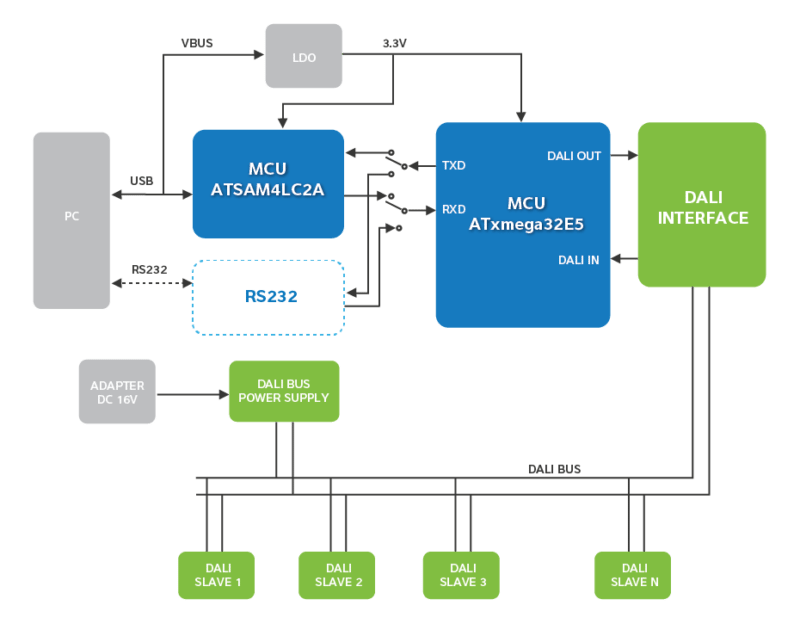
 This reference design implements a Master to control DALI slaves used in lighting control applications such as building automation and smart home. The design uses an Atmel ATxmega32E5 microcontroller. The system needs master, slaves, bus, bus power supply, USB cable, and PC. Both USB and RS232 communication interfaces are provided to connect to host system. The master software is installed on a PC and commands can be selected from the commands list through the GUI. Then, the user can control the addressed slave. The MCU can be programmed and debugged by connecting an external programming tool. For this reference design, the hardware design files (Schematic, BOM, and PCB Gerber) and software source code are provided. More on this Reference Design
DALI Slave with ATxmega MCU:

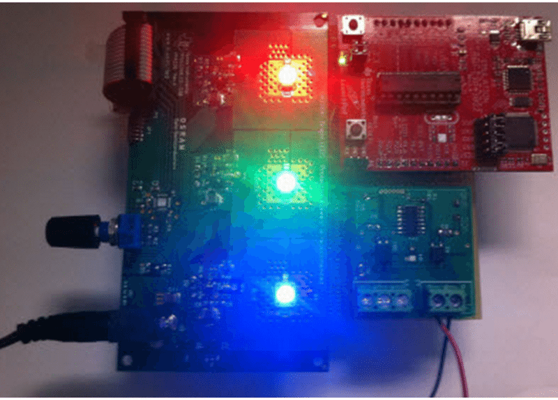
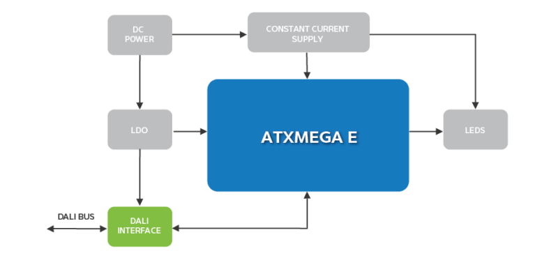
Here is a reference design of DALI Slave to control LED light strings based on ATxmega32E5. The master for this slave is discussed above. The hardware includes three parts: MCU, DALI physical layer interface and LED drive circuit. The MCU is used to communicate with the master and light source. The LED string is controlled by the commands through the MCU. The MCU can be programmed and debugged via PDI header. For this reference design, the hardware design files (schematic, BOM and PCB Gerber) and software source code are available. More on this Reference Design
Low-cost DALI Unit Using MCU:
This reference design describes a low-cost demonstration board to control illumination, for example, setting a lamp’s brightness level, turning on/off or dimming a lamp. It has a DALI master unit and four DALI slave units connected through a 2-wire DALI network. A Motorola MC68HC908KX8/KX2 microcontroller is used in a master-slave configuration. The master unit controls all the slave units and each slave unit can control a lamp. The LCD on the master shows the address and command data to be sent to the slave (for example, a lamp’s brightness level). Two shaft encoders can be turned to change the address and the command, and a push button is provided to send the data to the slave units. The software is re-programmable by using a built-in interface. More on this Reference Design
Feel interested! Check out other available reference designs.


