In this article, we will explore a straightforward method to create an IR remote-controlled FM radio with RDS (radio data system) using the ESP-01 module. We will utilise the Arduino IDE for software development and implementation.
Previously we designed the simple stereo Fm receiver circuit and FM Receiver Circuit.
This time, our primary goal is to design an affordable, compact, lightweight, and portable battery-operated Remote Controlled Stereo FM Radio with RDS message display, complete with IR remote control for user-friendly operation.
Note: We attached the demo video of this Stereo FM Radio project at the end of the article.
While there are several Arduino-based FM radios utilising modules like TEA5767, RDA5807M, and Si4703, they often come with drawbacks such as bulkiness, high power consumption, and excessive cost.
For instance, implementing an FM radio with an Arduino Uno requires a significant amount of power and is not cost-effective. Even the Arduino Nano, though smaller, is relatively expensive and requires a larger number of pins for soldering.
To tackle these limitations, we have chosen the ESP-01 module, which boasts four I/O pins, making it an ideal candidate for our radio. The ESP-01 is easy to program and assemble, requiring minimal expertise.
Unlike microcontroller-based designs, which demand additional components and pricey programmers, the ESP-01’s programming can be accomplished using an inexpensive USB-to-TTL converter.
Furthermore, there are numerous well-established Arduino libraries available for FM radio, IR remote control, and LCD/OLED displays, making software development a breeze.
For I2C communication with the FM radio module, we need two I/O pins. For IR remote control we need one I/O pin. With just three I/O pins we can implement an FM radio with IR remote control along with RDS display using a I2C display (LCD or OLED).
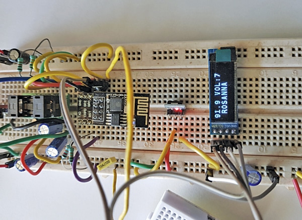
Banking on these advantages, we can quickly develop and integrate an FM radio with shortest development time using ESP-01. Fig. 1 shows the author’s prototype of Remote Controlled Stereo FM Radio with RDS using ESP-01.

To get started, let us look at the components required to build remote-controlled stereo FM radio-
| Table 1: Bill of Materials | |||
| S.No. | Description | Reference | Quantity |
| 1 | 220µF/16V electrolytic capacitor | C7, C8, C9 | 3 |
| 2 | 470µF/16V electrolytic capacitor | C6, C10 | 2 |
| 3 | 100nF capacitor | C1, C2, C4 | 3 |
| 4 | 22nF capacitor | C3 | 1 |
| 5 | LD1117V33 (TO-220) or AMS1117-3.3 (SOT-223) 3.3 volts fixed voltage regulator | IC1 | 1 |
| 6 | ESP-01 or ESP-01S | U1 | 1 |
| 7 | RDA5807M FM stereo module RRD-102 V2 | U2 | 1 |
| 8 | 4 pin 2.54mm header | LCD/OLED | 1 |
| 9 | 3.5mm stereo audio connector | X2 | 1 |
| 10 | 3.7V/500mAh lithium-ion battery | 1 | |
| 11 | TP4056 charger board | X1 | 1 |
| 12 | Micro USB cable | 1 | |
| 13 | Earphone or headphone, 32 ohms | 1 | |
| 14 | SWG#22 wire 75cm length for antenna | 1 | |
| 15 | 23mm 128×32 OLED display SSD1306 | 1 | |
| 16 | 38kHz IR 3.3V remote receiver and IR remote transmitter | U3 | 1 |
Remote Controlled Stereo FM Radio – Circuit
The circuit diagram for the remote-controlled stereo FM radio with RDS using the ESP-01 is depicted in Fig. 2.
It comprises the 3.3V voltage regulator LD117AV33 (IC1), ESP-01 (U1), RDA5807M FM stereo module RRD-102 V2 (U2), 38kHz IR remote receiver 3.3V module (U3), 23mm (0.91-inch) 128×32 OLED display SSD1306, 32-ohm earphones or headphones, and a few other components.
Oops! This is an EFY++ article, which means it's our Premium Content. You need to be a Registered User of our website to read its complete content.
Good News: You can register to our website for FREE! CLICK HERE to register now.
Already a registered member? If YES, then simply login to you account below. (TIP: Use 'forgot password' feature and reset and save your new password in your browser, if you forgot the last one!)


