 This door guard uses operational amplifier µA741 and a light-dependent resistor (LDR). Operational amplifier µA741 is used as a sensitive voltage comparator. Preset VR1 provides reference voltage to the non-inverting terminal (pin 3) of µA741. LDR1 and resistor R1 are connected to inverting pin 2 of IC1. LED1 and LDR1 are installed at opposite sides of entry such that light from LED1 falls on LDR1.
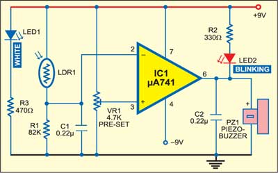
When the LED light is falling on LDR1, its resistance goes low in comparison to R1 and as a result pin, 2 of IC1 goes high. Consequently, output pin 6 of IC1 goes low and LED2 blinks while piezo buzzer PZ1 stops sounding. This indicates that the gate is closed.
When anyone opens the gate to enter or exit, the light from LED1 falling on LDR 1 is obstructed and its resistance goes very high. As a result, pin 2 of IC1 goes low and output pin 6 of IC1 goes high. LED2 stops blinking while the piezo buzzer sounds. This indicates that the gate is open.

This article is a part of the Top 10 LDR-based Electronics Projects. If you want to read more projects based on LDRs can go through this article.