


 This doorbell cum visitor indicator circuit can also give identification of the visitor to your home in your absence. When you’re home, you can use it simply as a normal doorbell.
Visitor indicator circuit
The circuit (see Fig. 1) comprises a monostable built around timer IC 555 (IC1), relay driver transistor BC548 (T1), inverter section built around IC 7404 (IC2), latching section built around IC 555 (IC3) and LED display driver transistor BC548 (T2).
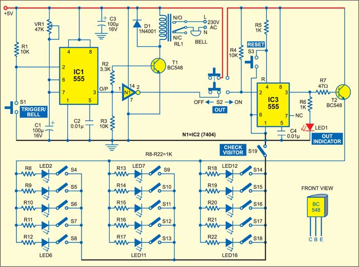
The monostable output drives the relay through transistor amplifier T1. The normally-opened (N/O) contact of the relay connects an electric bell with mains supply as shown in Fig. 1. The output of the monostable also goes to inverter N1, which, in turn, enables the latching circuit built around IC3 in conjunction with DPDT slide switch S2. The output of IC3 at its pin 3 is fed to LED1 (visitor-out indicator) and LED2 through LED16 via LED driver transistor T2.

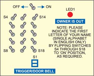
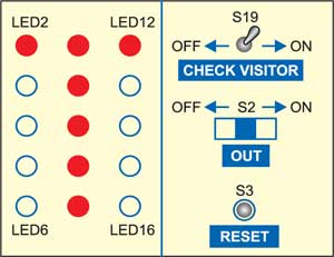
The switch panel shown in Fig. 2 is to be mounted on the entry gate or door, while the LED display panel shown in Fig. 3 is to be kept inside the house near the owner’s desk.
Circuit operation
Before you leave your house, slide switch S2 (Out) to ‘on’ position and press reset switch S3 once. When somebody visits your home and presses doorbell switch S1, it will trigger the monostable (IC1) and also energise the relay to ring the bell. The monostable output through inverter N1 will enable the latching circuit and LED1 will glow continuously to indicate that you’re out of the house.

The message “Please indicate the first letter of your name (single alphabet in English only) by flipping switches S4 through S18 to ‘on’ position,” as required, is written just below LED1 indicator as shown in Fig. 2.
Suppose the visitor’s name is Tina Chopra. As the initial alphabet of her first name is ‘T,’ she has to flip the topmost-row and middle-column switches towards ‘on’ position. The position of the switches for this example is shown in Fig. 2.
When you return home, just flip switch S19 to ‘on’ position to check the visitor’s initial. The topmost-row and middle-column LEDs will glow to indicate the alphabet ‘T,’ so you know that one of your friends having name starting with ‘T’ had visited your place in your absence. The status of the LEDs for this example is shown in Fig. 3 by the red LEDs.
Now you can slide switch S2 to ‘off’ position or press reset button S3 once. When the indicator is not in use, slide DPDT switch S2 to ‘off’ position to bypass the latching and LED display sections by cutting off the power supply and thus prevent unnecessary continuous drain of power. Now the rest of the circuit will work as a doorbell only.
The rows and columns may be increased to accommodate a 5×7 display matrix. The circuit can be used for a single visitor only.
The article was first published in September 2005 and has recently been updated.


Its a nice and useable project,i wish if you have added pcb layout for same
Why is it called cum?
used in hyphenated phrases to link nouns that describe a person or thing with two jobs, uses, etc.