 You can install this system in the driveway itself to detect intrusion by a vehicle, person or large animal. It sounds an alarm when any intrusion takes place.

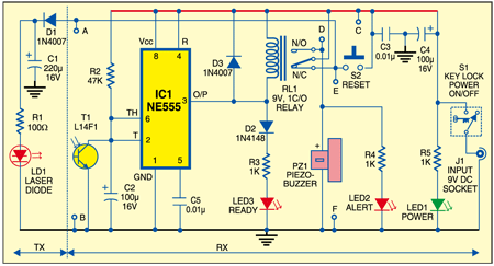
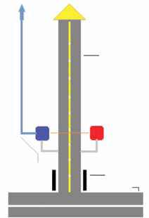
As shown in Fig. 1, the system comprises two modules: transmitter and receiver. The transmitter module (TX) is wired around a handheld laser pointer device (LD1). The laser pointer is powered by the 9V DC supply available from the receiver module (RX). Installation of the transmitter and receiver modules is shown in Fig. 2. Resistor R1 limits the current flowing through the laser pointer (LD1).

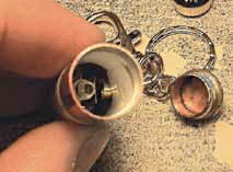
Laser pointers are not designed to be taken apart. So the following method might be used to connect the external power supply to the laser diode without damaging the pointer itself: Take two short lengths of flex-ible wires with small metal clips soldered at their one end. Insert one of the metal clips inside the body of the pointer and connect to the battery contact spring. Hold the laser on/off switch closed with a small cable tie. The other clip can then be connected to the body of the laser torch through R1. As laser pointers are not designed for this type of application, select the value of R1 carefully.
The receiver module (RX) is a com-pact light-controlled security switch, powered by an external power adap-tor (230V AC 50Hz/9V DC 250mA). A key-lock switch (S1) controls the power supply to the receiver module. There are two LEDs on the front panel for power (LED1) and visitor alert (LED2).
Reset switch S2 on the front panel can be used to clear the alert signal after detection of a driveway activity. LED3 indicates that the system is ready.
Working of the receiver module is very simple. Initially, when power is applied to the system, it is in standby mode. LED1 indi-cates the presence of power and LED3 lights up to indicate that the laser beam from the transmit-ter module is falling on the pho-tosensor (T1) of the receiver module. When the laser beam is interrupted by a person, animal or object, the photo-sensor energises the rest of the circuit and the piezobuzzer sounds.
Assemble the circuit on a general-purpose PCB. Fabricate the transmitter, receiver and the control panel (an ex-tension of the receiver module) as three independent units, sharing a common power supply. House these units in suitable waterproof plastic enclosures and interconnect using high-quality cables.
Install the transmitter and re-ceiver modules far enough from the driveway edge so that the vehicles are unlikely to hit these. Place the transmitter module on one side of the driveway, approximately one metre (or 3 feet) above the floor level using a standard PVC pipe. Now place the receiver module on the opposite side (about one metre above the floor us-ing a standard PVC pipe) directly facing the transmitter module. Run the dual-core (A-B) transmitter power cable through the PVC mounting post and plug it into the receiver module. It is recommended that you run this interconnection crossing cable inside the PVC conduit to prevent accidental damage. Route the quad-core (termi-nals C, D, E and F) system cable to the control panel location.

The wiring arrangement is shown in Fig. 3. With proper setup of both the modules, the laser beam is so intense that even direct sunlight cannot affect operation of the alarm system.

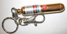
Test the system by having someone drive an automobile past the detection system. The alarm should sound when the vehicle crosses the laser beam. You may need to adjust the position of the modules for optimal result. During ini-tial setup, it may be necessary to short-circuit the terminals of reset switch S2 using a short jumper wire. Fig. 4 shows the photo of the laser pointer, while Fig. 5 shows the inner view of the laser pointer.

Caution. Use the laser pointer care-fully as it may severely damage the eye or skin


