


 In mains powered equipment, exposed metal parts are connected to earth wire in order to prevent users from contact with high voltages if electrical insulation fails. Connections to ground through earth connection also limit the build-up of static electricity when handling electrostatic-sensitive devices. Earth in a mains electrical wiring system is a conductor that provides a low-impedance path to the earth to prevent hazardous voltages from appearing on equipment and hence the name.
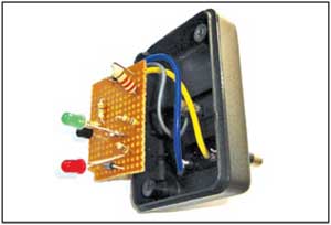
Here is a simple earth fault indicator to find whether the mains wiring is correct or not. This tester can be used to check sockets periodically before connecting appliances like heater and electric iron. It indicates the status of the mains wiring through two LEDs as shown in Fig. 1.
Earth fault indicator circuit
Fig. 2 shows the circuit of earth fault indicator. The circuit is built around a BC547 transistor (T1), two LEDs (LED1 and LED2), two 1N4007 diodes (D1 and D2) and five resistors (R1 through R5).

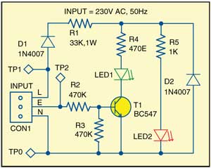
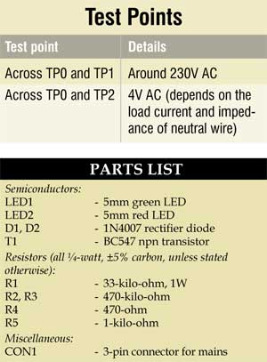
The circuit takes advantage of the voltage that appears across the earth and neutral terminals. Neutral-to-earth voltage as measured at the load for a single-phase circuit is a function of the load current and the impedance of the neutral wire. Various standards limit this voltage drop in a branch circuit to 3 per cent (5 per cent total for feeder and branch circuit) for a reasonable efficiency of operation. Based on this, the neutral-to-earth voltage limit for a single-phase 120V AC circuit is 3.6V AC and for a single-phase 230V AC circuit 6.6V AC.
There is no additional power supply used to operate this circuit. The circuit is directly powered from the 230V AC mains supply. The combination of diode D1 and resistor R1 reduces the 230V AC mains to a low voltage for the circuit. A transistor switch is provided to light up the green LED (LED1) if earth is correctly connected. The base of T1 is connected to earth pin of the mains supply through a network of resistors R2 and R3 as shown in Fig. 2.

Circuit operation
The red LED (LED2) lights up if there is power in the socket and phase (L) and neutral (N) lines are connected correctly. Diode D2 protects the green LED (LED1) from damage when the polarity changes. Resistors R4 and R5 limit current through LED1 and LED2, respectively.
When the mains wiring is proper, a potential difference develops between the neutral (N) and earth (E) lines and transistor T1 turns on to light up the green LED (LED1). This indicates that the earth connection is perfect. At the same time, the red LED also glows, indicating that the phase (L) and neutral (N) lines are connected properly. In brief, if the phase, neutral and earth connections are proper, both the red and green LEDs light up. When the earth connection is broken, the red LED2 glows but green LED1 does not.
Construction and testing
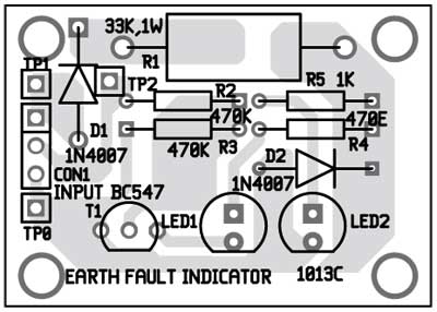
A single side PCB for the earth fault indicator is shown in Fig. 3 and its component layout in Fig. 4. After assembling the circuit on a PCB, enclose it in a suitable plastic case. The circuit can be housed in an adapter box with three pins (see Fig. 1).
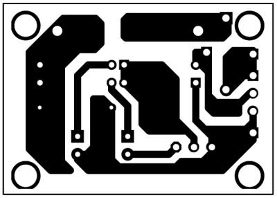
Download PCB and component layout PDFs: click here
To test the circuit for proper functioning, check input supply at TP1 with respect to TP0. Also check the voltage difference across neutral and earth pins as per the test point table.
EFY note: As the circuit is operated directly from the mains voltage, it should be assembled only by experienced persons. To avoid lethal shock, do not touch or troubleshoot the circuit when it is connected to mains power.
Feel interested? Check out other circuits in the circuits section.
Hello,
I have tested the circuit and it does not work with the connection setup shown in the diagram.
It worked when I change the L and N connections. In this situation the green LED goes on even with a bad earth connection with a very high voltage difference with null wire.
can you explain about this?
Regards,
M.R.Mahdavifar
Can we have an audio alarm
Your Result Is Ok Or Not…
Because Your Question is Alarm detect in Audio side
so please contact me..
7066727948
not working green led always glowing
Sir, can you please send Proteus design of this project.
Please share your conatact details for discuss on project beacuse i have one project for you and i will pay you best as you want …
Please do needful