


Smart hardware design can simplify the embedded software and make it more reliable. Designers use blinking LED signals to indicate different status and for inbuilt testability. Making an LED array blink requires an individual software loop for each LED or an individual timer and specific software to serve it. This can be an issue in a system that uses low-level MCUs which provide limited resources.
The circuit presented here solves this problem by adding a simple hardware comprising low-cost inverters with Schmitt trigger for blinking as many LEDs as required.
Circuit and working
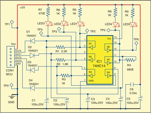
Fig. 1 shows the circuit for efficient LED blinking for embedded systems. It uses different arrangements to make five different LEDs (LED1 through LED5) blink at individual rates. The circuit is built around 74HC14 (IC1) containing six inverters with Schmitt triggers at the inputs. The frequency of blinking is usually selected in the 0.2-20Hz range.

The combination of inverter N1, resistor R1 and capacitor C1 is used as a square wave generator to blink LED1. LED1 blinks when output OUT0 from the MCU is high and goes off when output OUT0 is low.

The combination of inverter N2, resistor R2 and capacitor C2 works as a second square wave generator that makes LED2 blink. LED2 blinks when output OUT1 of the MCU is low and glows constantly when the output is high due to reverse orientation of D2.
Sometimes an LED needs more current than that provided by a single inverter. In that case, two or more inverters can be connected in parallel. Such an arrangement is made using inverters N3 and N4, resistor R3 and capacitor C3. The direction of diode D3 determines the logic of control of LED3 as indicated in the previous arrangements.
If you want two LEDs blinking alternately, the setup is made using inverters N5 and N6 together with resistor R4 and capacitor C4.
When OUT3 is low, LED4 is ‘off’ and LED5 is ‘on.’ When OUT3 is high, LED4 and LED5 blink alternately. The frequency of blinking in all the cases depends on the value of the adjoining resistor and capacitor.
Download PCB and component layout PDFs: click here
Construction and testing
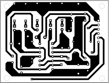
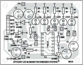
An actual-size, single-side PCB for efficient LED blinking for embedded systems is shown in Fig. 2 and its component layout in Fig. 3. The PCB provided is only for learning purpose and can be enclosed in a suitable case.
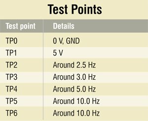
To test the circuit, measure input supply at TP1. It should be around 5V DC with respect to TP0. Now make OUT0 high and measure the frequency at TP2. It should be around 2.5 Hz. Similarly, measure the frequencies at test points TP3, TP4, TP5 and TP6 as shown in the test points table.
The author is a regular contributor to EFY. He was a researcher and assistant professor in Technical University of Sofia (Bulgaria) and lecturer in Kingdom of Morocco. Now he is working as an electronics engineer in the private sector of Bulgaria


sir I want your suggestion regarding 4th year project.. As I enter in to 5 thsemester I have to think for that…I Am. very much interested in VLSI and microprocessor
Kindly elaborate your query.
SIR IS THERE ANY PROJECTS REGARDING LIGHT FIDELITY(LI-FI) PROJECTS
Sir,can you tell me how you are calculating frequency
Sir, I need to write automated python scripts for testing. How do i check automatically whether LED is on or not for some error indication.