 None of us likes bugs at home. To kill these flying insects, they should first be attracted and then electrocuted. An electric fly swatter is one such device with a high voltage electrocuting circuit and an insect attracting UV lamp of 365 nm wavelength. This ultraviolet fluorescent lamp is mounted in the middle of the cabinet and a pair of carefully spaced, electrically insulated, charged wire grids surround the light.
When an insect comes close enough to the mesh pair, an electrical arc is formed, the dielectric breaks down and current flows through the insect’s body. Electrocuting the insect doesn’t require it to touch both the wires as an arc forms in the air gap over 1800 V.
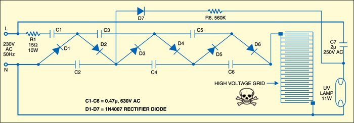
Electric fly swatter circuit

In the schematic, the grid is charged to 1800V by the voltage multiplier built around diodes D1 through D6 and capacitors C1 through C6. When a bug passes through the grid, the high grid voltage causes a discharge though the bug, the grid voltage reduces and the stored voltage kills the bug instantly.
To ignite the UV lamp, a voltage tapping is provided from the volt-age multiplier circuit. At switch-on, around 700V ionises the gas in the tubelight and capacitor C7 discharges through the tube, lowering the resistance enough to sustain continual AC current flow. C7 then continues to act as the ballast.
Construction & testing
Assemble the circuit on a general purpose PCB and enclose in a small rectangular cabinet. Fix the UV lamp and the assembled PCB inside the cabinet. Mount the high voltage grid outside the cabinet on the front panel. Now your electric bug zapper is ready to use.
EFY warning
As the circuit works on a high voltage, don’t touch the grid with bare hands to avoid electric shock, which can be dangerous!
The article was first published in May 2010 and has recently been updated.


This circuit is nice, it really basic and easy to understand, but I have 3 question
1. If I were working with a lower voltage say 3v will increasing the amount of capacitor & diode meet up the 1800v requirement?
2. If I have another type of uv light that works on 230v, by connecting it direct to the 230v, will it affect the bulb?
3. In the schematics you said the 560k resistor is r6, is that some kind of error?
Please help me out ASAP
I hv same doubt,
What will b the ckt if i wanr to run tube on 3v battery in out
Pls suggest the ckt