


 This is a fantastic circuit for self-protection. In case a burglar intrudes your house, you can use this electric shock gun as a weapon for self-protection by giving a mild electric shock to the attacker.
This circuit comprises astable multivibrator, inverter, and voltage quadrupler sections. The astable multvibrator is designed for 1 kHz with a 9V DC supply. The inverter section consists of switching transistors and an inverter transformer. The primary of transformer is of 9V-0-9V and the secondary is of 100V, 100mA. For compatibility, a driver transformer that is used in radio is used as the inverter transformer. The secondary output current of 100 mA gives a good enough shock to human body.
Electric Shock Gun Circuit
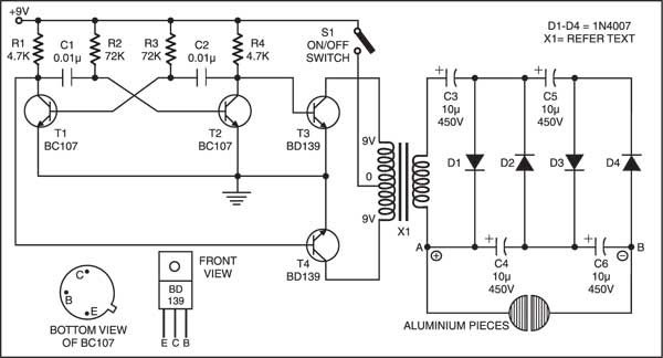
The astable multivibrator consists of two BC107 transistors (T1 and T2), two 0.01µF capacitors (C1 and C2), two 4.7-kilo-ohm resistors (R1 and R4), and two 72-kilo-ohm resistors (R2 and R3). A squarewave output of 1 kHz (with a phase shift of 180 degrees) is obtained at the collector of transistor T1 or T2. This squarewave output is given to the base of switching transistors BD139 (T3 and T4).

The collectors of transistors T3 and T4 are connected to the primary of the transformer and their emitters are grounded. A DC supply of +9V is also applied to the center-tapping of transformer X1 through switch S1. This is an inverter action, so we get around 100V AC at the secondary of the transformer. This AC is given to a quadrupler circuit consisting of capacitors C3 through C6 and diodes D1 through D4.
The voltage quadrupler develops a DC voltage output equal to three or four times the input AC voltage. During the first positive half cycle, diode D1 conducts, charging C1 to Vm with polarity as shown in Fig. 1. During the first negative half cycle, diode D2 conducts, charging C2 to 2Vm. Diodes D1 and D3 conduct during the second positive half cycle, charging capacitors C1 and C3, while the voltage across capacitor C2 charges capacitor C3 to the same value 2Vm. During the second negative half cycle, diodes D2 and D4 conduct and capacitor C3 charges C4 to 2Vm. Thus, the voltage across C2 is 2Vm, across C1 and C3 is 3Vm, and across C2 and C4 is 4Vm. Therefore we get around 350V at the output of voltage quadrupler (across points A and B, as shown in Fig. 1).

Circuit operation
Press the pushbutton switch (S1) of the circuit and touch the output connectors to any object. There will be a heavy electric discharge, which is enough for a good shock.
The circuit assembly and testing procedure is as follows:
- Use a can type +9V battery for Vcc.
- The transformer (X1) is designed to have 9V-0-9V primary and 100V, 100mA secondary, with primary winding having 80 turns (40+40, i.e. centre tapping at 40th turn) of 26 or 27 SWG and secondary winding having 450 turns of 35 or 36 SWG.
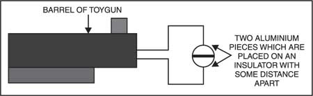
- Mount the circuit in a toy gun with output connectors at the front end of the barrel. The output connectors may be connected to two aluminium pieces with an insulator placed between them to avoid short circuit. The arrangement is shown in Fig. 2.
- Press switch S1 (here the trigger point of toy gun) and touch the front end of the barrel of toy gun to a person. The current in the voltage quadrupler will get discharged through the metal or aluminium pieces via the human body and the person will feel the electric shock.
Note of caution:
Check the circuit thoroughly before testing on anyone and use it judiciously, only when necessary.
The article was published in April 2003 & has been recently updated.

How it will produce 100v ac if we give 9v dc supply?
why are you using BD139 transistor?
There is no Ground indicated for the 9VDC Battery.