 In most water level monitors and alarms, corrosion of the probes makes the systems unusable in a few months. This water level alarm uses a phase-locked loop (PLL) circuit to generate a particular frequency at its probes to avoid electrolysis of the water. The circuit uses two NE567 PLL ICs.
Water level alarm circuit
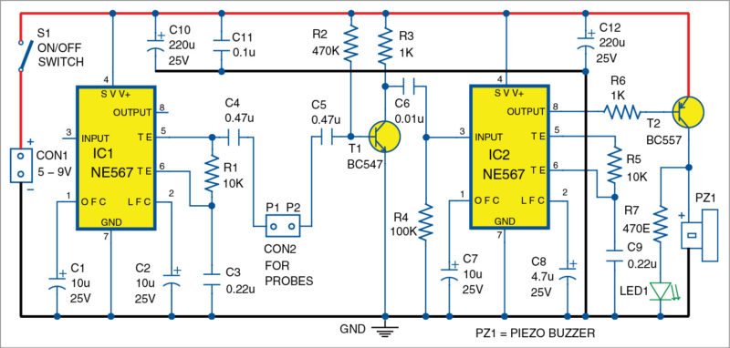
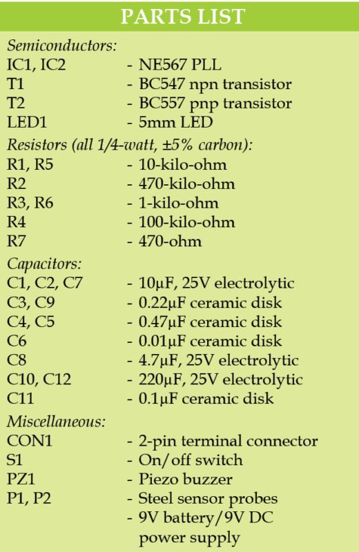
Circuit diagram of the electrolysis free water level alarm is shown in Fig. 1. It is built around two NE567 ICs (IC1 and IC2), npn transistor BC547 (T1), pnp transistor BC557 (T2) and piezo buzzer (PZ1), along with a few other components.

IC1 generates around 500Hz signals through its voltage-controlled oscillator, which is applied to first probe P1. When P1 gets shorted with second probe P2 via water, IC2 decodes this signal and activates buzzer PZ1. When a frequency of around 500Hz is received by IC2, its output pin 8 goes low. This makes pnp transistor T2 to conduct, which, in turn, makes LED1 glow and PZ1 beep.
As the signal is passed through water, there is no electrolysis and, hence, corrosion of the probes (P1 and P2) does not occur.
The circuit works off any 5V DC to 9V DC power supply.

Construction and testing
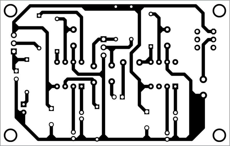
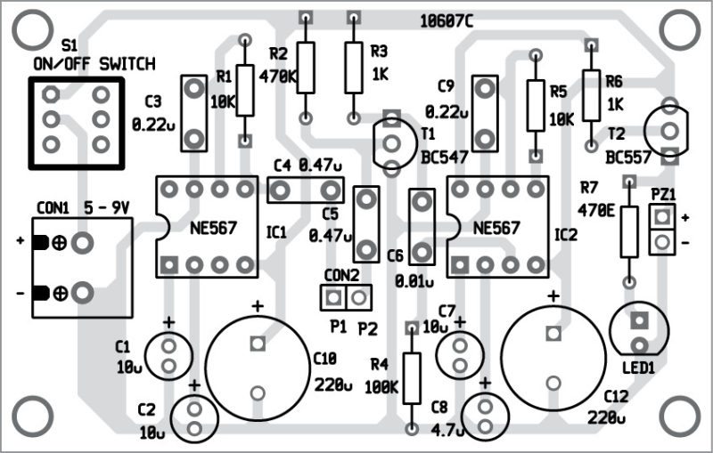
A single-side PCB layout for the electrolysis free water level alarm is shown in Fig. 2 and its component layout in Fig. 3. After assembling the circuit on the PCB, enclose it in a plastic box and connect the sensors using a two-wire cable to the PCB.


Install the probes in the overhead tank in such a way that when the tank gets filled, both probes get shorted through water.
Download PCB and component layout PDFs: click here
Feel interested? Check out more electronics project.


Can reduce one ic , if no use buzzer. I like to use one relay with driver transister please inform me
I can’t understand exact working of electolysis free water level alarm.so,please guide me and send pdf file of working
kindly explain the working concept of above water level alarm