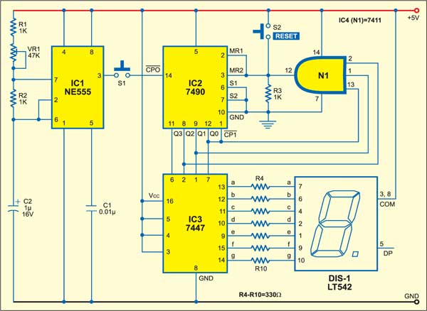
 This electronic dice has no chance of wear and tear but all the features of a wooden or plastic dice used for Ludo game.
Electronic dice circuit
The circuit comprises an astable multivibrator built around timer IC NE555 (IC1) whose time period (T) is approximately 0.02 second. It drives decade counter IC 74LS90 (IC2) through pushbutton switch S1. The outputs of the decade counter are fed to decoder/driver IC 7447 (IC3), which, in turn, is connected to common-cathode, 7-segment display LTS542 (DIS-1). The Q0 through Q2 outputs of the decade counter also go to 3-input AND gate N1 (IC4).

At the count of binary 7 (i.e., when Q0, Q1 and Q2 all become high) of the decade counter, the output of the AND gate (N1) goes high to reset counter IC1.
For playing the game, a player presses switch S1 momentarily. The display will show any count between ‘1’ and ‘6.’ Push-to-on switch S2 is used for resetting counter IC1 so that the display shows ‘0’ before a player is allowed to play.
Construction & testing
Assemble the circuit on a small, general-purpose PCB along with switches S1 and S2.
The article was first published in March 2006 and has recently been updated.


