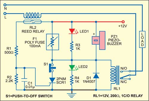
 An absolute necessity of every electronics lab is a workbench power supply. The power supply should be regulated and protected against short circuit. Most power-supply protection circuits use a low-value, high-wattage resistor connected in series with the load for current sensing. The voltage drop across the sensor resistor is weighed to activate the protection circuit. The given electronic fuse circuit is based on a poly-fuse application, which is a re-settable fuse by itself.
Electronic fuse circuit

Circuit operation
Initially, when the circuit is powered, silicon-controlled rectifier SCR1 is ‘off.’ Relay RL1 energizes through the polyfuse and the load is connected through the normally opened (N/O) contact of the relay. When the current drawn by the load increases above a certain level (which depends on the number of turns in the winding on reed relay, see Fig. 2 and the accompanying table), the contacts of reed relay RL2 close to trigger SCR1. As a result, relay RL1 de-energises and the load gets disconnected. The polyfuse remains in high-resistance state until SCR1 is turned off.

 The circuit can be reset either by switching off the power supply or by pushing reset switch S1. LED2 indicates that the power supply is working normally. LED1 indicates that the power supply unit is under the protection mode and the buzzer sounds to warn the user.
The turns of reed relay winding are based on the current drawn through the load, so refer to the table for winding details for your load current requirements. At EFY, testing was done for approximately 1.85A AC load current at 230V AC mains and accordingly 16 turns of 22SWG copper-enameled wire were wound on the reed relay.
The article was first published in October 2005 and has recently been updated.


