


 Here is a circuit that simulates the chirping and glow of a glow-worm bug. The circuit is built around timer IC 7555 (IC1), which is wired as an astable multivibrator with a frequency of about 2.5 Hz. Other values of resistors R2 and R3 and capacitor C1 can be used if a different flashing rate is required.
The output from pin 3 of IC1 alternates between 0V and 3V, resulting in flashing of the four LEDs (LED1 through LED4). As the voltage across the LEDs is low, these do not need series resistors. An audible warning device (AWD), such as a simple piezobuzzer, is wired in parallel to the LEDs. It must be rated to operate off 3V.
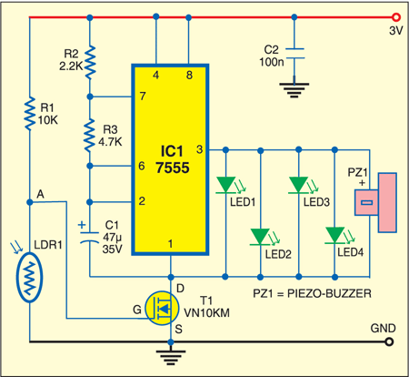
The LEDs together with the piezobuzzer produce the combined effect of an intermittent note or a warbling note and also flashing of light. Light-dependent resistor LDR1 is used to provide the light-sensitive response of the bug. Connected in series with resistor R1, it forms a potential divider. The voltage across the combination of these resistors is 3V, while the voltage across each resistor is proportional to its resistance. For example, in ambient light, the LDR has a resistance of about 10 kilo-ohms. The voltage across LDR1 at point A is 1.5V or less, which is insufficient to turn on the MOSFET (T1). So no current flows through it and the astable circuit does not operate.

When it’s dark, the resistance of LDR1 rises to about 500 kilo-ohms or more and the voltage across it rises above 1.5V, turning on T1. Now current flows through T1 to turn on the astable multivibrator. As a result, the LEDs and AWD are switched on.
Assemble the circuit on a general-purpose PCB shaped as a bug as shown in Fig. 2. Mount two wires on the circuit board and bend these to resemble a pair of antennae.

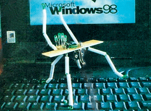
Mount the battery holder box on the solder side of the PCB. The pair of studs on the box looks like a pair of eyes. Mount the components such that the arrangement has symmetrical appearance. Bend around the long leads of LDR1 to make it look like a proboscis (protruding mouth part). Place the main circuit board cross-ways across the battery box so that the PCB looks like a pair of wings. Mount the components on the central area of the PCB leaving the actual wings clear. After checking the circuit, glue tufts of coloured cotton wool over the components.
Make the legs by cutting a 4mm diameter white polystyrene tubing into suitable lengths. Use a single-core hook-up wire. Double-sided self-adhesive pads may be useful for holding the components together, particularly for fixing the circuit board and the AWD in place.

where do we use these electronic glow worms? please post the applications.