With this electronic heart glowing on and off, you are sure to steal the heart of that special someone. The circuit uses an NE555 timer wired in astable multivibrator mode. Its frequency of oscillations is determined by resistors R1 and R2 and capacitor C2. Here the frequency is approximately 0.2 Hz. Each period lasts for just a little over 4 seconds.
Capacitor C2 charges and discharges exponentially with time. As a result, a sawtooth waveform appears to be a ramp. Whatever be the voltage across the capacitor, it may not be utilised directly, as this will serve only to discharge/drain the capacitor.
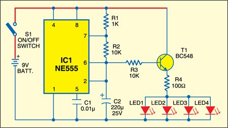

Transistor BC548 operating in the common-emitter mode acts as a buffer, preventing loading of capacitor C2, and thereby not affecting the frequency of operation of NE555. Its emitter is connected to the four red LEDs in parallel, via a 100-ohm resistor.
The output at pin 6 of IC1 is used here as the source of a sawtooth waveform. It results in a gradual and smooth illumination/dimming of the LEDs.

By changing the emitter resistance, you can get the maximum voltage across the LED. If the resistance value is too small, the light output of the LEDs may appear to be a clipped sawtooth. If it’s too large, the LEDs will turn off for a fraction of the period. When maintained at 100 ohms, the LEDs appear to follow the voltage smoothly.
Assemble the circuit on a general-purpose PCB and place in a heart made of styrofoam. Mount switch S1 at the side of the heart. Press it and the heart will start glowing on and off. The results will be best observed in darkness.