


 An electronic thermostat is a standard equipment for sensing the temperature of a system and maintaining it at a pre-defined point. It is a regular feature in air-conditioners, room heaters and refrigerators. Although some commercially-available refrigerators have inbuilt thermostats, the given circuit is easy to build and automatically turns on or turns off the appliance at pre-set temperatures.
My refrigerator’s deep freezer’s temperature remains between -5°C to -15°C (former temperature switches the fridge on and the latter turns it off).
Electronic thermostat circuit
The 230V AC mains voltage instead of going directly to the refrigerator (or input of the automatic voltage stabiliser, if used with the fridge) is routed through the normally open (N/O) contact of relay RL1. When the relay gets energised due to conduction of T2 (BC547), relay contact is closed and the appliance gets 230V AC power, which, in turn, starts cooling.

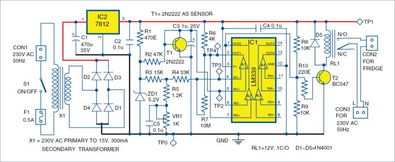
IC1 is a quad comparator (LM339) used as a voltage comparator with hysteresis. Inverting input of IC1 is applied to a reference voltage derived from Zener diode ZD1 (5.2V), which is then further divided by the potential divider arrangement provided by R3, R5 and VR1. C5 is the decoupling capacitor to bypass AC noise, if any.
Heart of the circuit
Between the non-inverting input of IC1 and the ground is the temperature sensor, which is an npn silicon transistor 2N2222 with its collector shorted to its base. The transistor’s temperature-dependent characteristic of the base-emitter junction is used as the temperature-sensing property. For every degree rise, junction voltage decreases by 2mV. Trimpot VR1 is adjusted to the reference voltage at a value equal to the sensor’s junction voltage corresponding to the lower negative temperature (-5°C in this case).
On state
If temperature inside the fridge is between -5°C and -15°C, then voltage at the inverting input of the comparator is equal to reference voltage (corresponding to voltage for -5°C) plus fraction of the voltage feedback through potential dividers R7 and R4. Feedback voltage in this case is 20mV corresponding to a temperature change of 10°C. Thus, as long as temperature is more than -15°C, voltage at inverting input is greater than that at non-inverting input, comparator output pin 2 is high, T2 is saturated and energises the relay coil and the appliance remains switched on.
Off state
When temperature goes below -15°C, comparator output goes low, relay gets de-energised and the appliance goes into off state. When comparator goes low, feedback voltage of 20mV vanishes and voltage at the inverting input corresponds to a temperature of -5°C. So the temperature cycles between -5°C and -15°C.
Reference setting using VR1 decides the less negative of the two temperature extremes and the hysteresis depends on the voltage divider arrangement of R7 and R4.
Let ‘T’ be the desired temperature hysteresis, then,
T (°C)=(3000×R4)/(R4+R7)
Power supply
DC supply for the circuit including the relay consists of a conventional bridge rectifier, step-down transformer X1 and filter capacitor C1, along with 3-terminal voltage regulator 7812. C2 is a decoupling capacitor commonly used at the output of the voltage regulator.
Construction and testing
A PCB layout of the electronic thermostat circuit for a fridge is shown Fig. 2 and its component layout in Fig. 3.

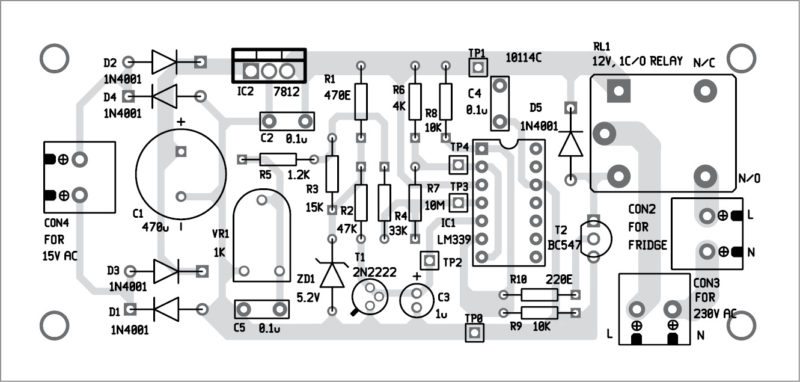
Download PCB and component layout PDFs: click here
Sensor transistor 2N2222 should be mounted on the side wall of the freezer with some epoxy (like Araldite). Connections from the sensor to the circuit should be made with a shielded cable made of materials like polycab coatings. Leads should be fully insulated from each other and from the transistor body using some epoxy so that water deposition on the sensor does not short these.

I housed the sensor’s metallic body in a ceramic block and affixed it to the freezer’s body. This fitting is quite tight to ensure complete thermal contact. Ceramic is the best thermal conductor and electrical insulator.
Calibration is done by bringing the sensor in contact with ice water and at the same time biasing its base emitter junction at about 100µA using a series resistance and suitable voltage. Junction voltage thus observed corresponds to 0°C. Junction voltage corresponding to any other temperature can then be determined from the figure of temperature coefficient (-5mV/°C).
For troubleshooting, ensure various test points are as per the voltages listed in the test point table.
The project was originally published in May 2016 and has recently been updated.


Hi
Little complicated
But you explained very well
Thank you for your feedback.
Here’s the reply from the author Sundar B. “Thank you Mr. Potdar. Please try the circuit at home, its not that complicated; you will enjoy it as you progress. Building home automation is my favorite leisure work and also forte. If you have basic Physics knowledge, to the level of FYBSc, this circuit can be built from ICs and other components sold by any electronic circuit stores. In Mumbai, there are many at Lamington Road, which supply or ship the goods via phone call too to your city… Please google Gala Electronics. They also advertise in EFY”
Congratulations , it’s a good project well explained. But….
How about 1) DEFROST 2)ON-DELAY 3) Over/Under Voltage PROTECTION
All that could be added easily and is essential for a practically viable circuit
Here’s the reply from the author Sundar B.
“Thank you Mr. Vishwa, for deeply probing the circuit and finding the additional possibility. Well, essentially Defrost detector can be interfaced with the relevant sensor. I am not clear with what you meant by “ON-DELAY”, please elaborate on that so that I can work on it. Regarding Over/Under Voltage Protection, indeed, it can be built and I will be publishing that as separate circuit with more system integration such as remote monitoring of the refrigeration (especially for industries which I am building that involves wireless monitoring of multiple parameters on a 16-Bit Microcontroller). Once I am done with the System Integration and Field Tested/Commissioned, barring the proprietor data and systems, I will be scaling down the same for 8-bit Microcontroller with a Zigbee Interface. Please wait till then. I am very glad with the inputs that are true source of encouragement.”