This article covers the major differences between isolated amplifier-based and isolated modulator-based solutions, and explains their uses in improving the overall efficiency and power throughput in various industrial and automotive applications.
Industrial applications such as motor drives, photovoltaic inverters, and uninterruptible power supplies (UPS), and automotive applications such as onboard chargers, traction inverters, and DC-DC converters operate at high voltage and current levels to optimise the overall efficiency and power throughput. These systems are subjected to hostile environments such as electrical noise, vibration, mechanical shock, extreme temperatures, ingress of contaminants, and so on.
Such systems demand robust, reliable, and galvanic isolation to isolate high voltages from low-voltage circuits. The feedback signals measured on these high voltages are galvanically isolated from the low-voltage controllers by isolated amplifiers or isolated modulators. This article compares isolated amplifier and isolated modulator-based solutions and explains some unique advantages of isolated modulator-based solutions.
Introduction to isolated amplifiers
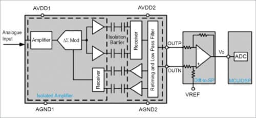
Fig. 1 shows the implementation of an isolated amplifier-based measurement solution.
The received bitstream and clock are synchronised and processed by an analogue low-pass filter on the low voltage side and presented as an analogue output signal. The differential output of the isolated amplifier is often converted to a single-ended analogue output with an op-amp-based circuit. This op-amp-based circuit can also implement a low-pass filter to further reduce the signal bandwidth to a bandwidth of interest and thereby improve the system’s noise performance. The analogue-to-digital converter (ADC), either external or internal to the microcontroller (MCU) or digital signal processor (DSP), receives this feedback analogue output and converts this output back to the digital domain.
Introduction to isolated modulators
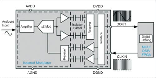
Fig. 2 shows the implementation of an isolated modulator-based measurement solution.
The input stage of an isolated modulator is similar to that of an isolated amplifier. The drivers transfer the modulator output across the isolation barrier. The isolated data output provides a digital bitstream of 1’s and 0’s at a much higher frequency (up to 20MHz). The average time of this bitstream output is proportional to the analogue input voltage. The measured signal is reconstructed with a digital filter inside the microcontroller families such as the TMS320F2807x and TMS320F2837x, DSP, or field-programmable gate array (FPGA).
Performance comparison between isolated amplifiers and isolated modulators
In an isolated amplifier-based solution, the measured analogue signal undergoes several analogue-to-digital and digital-to-analogue conversions. The stages within the isolated amplifier, differential-to-single-ended stage, and ADC reduce overall accuracy and noise performance and increase latency.
The fixed low-pass filter implementation in the output stage of the isolated amplifier limits the signal bandwidth. An external op-amp-based circuit used for differential-to-single-ended conversions can be used to create an active low-pass filter to further limit the signal bandwidth and thereby improve noise performance.
The isolated amplifier has a fixed latency. Isolated amplifier-based solutions are widely used because of familiarity and relative ease in implementation. As shown in Fig. 2, the measured analogue signal in an isolated modulator-based solution undergoes only one analogue-to-digital conversion. This solution eliminates the need for a differential-to-single-ended stage, thereby reducing the number of components and solution size.
The ADC used in an isolated amplifier based solution, which in many situations limits the maximum achievable sample resolution and accuracy, is not needed anymore. This isolated modulator-based approach has improved signal-noise performance, overall accuracy and can achieve higher signal bandwidth and lower latency than an isolated amplifier-based solution.

Isolated modulators provide a much faster digital bitstream output, typically up to 20MHz. The sigma-delta filter module (SDFM) module inside the microcontroller families (such as the TMS320F2807x and TMS320F2837x) provides an easy way to tune the noise performance, signal bandwidth, or latency.
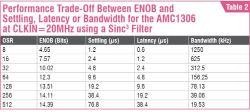
As shown in Table 2, a higher oversampling ratio (OSR) implementation leads to better accuracy and higher sample resolution but less signal bandwidth and higher latency. Similarly, lowering OSR reduces accuracy and sample resolution but increases bandwidth and reduces latency.
A similar DSP or an FPGA can also implement such a digital filter.
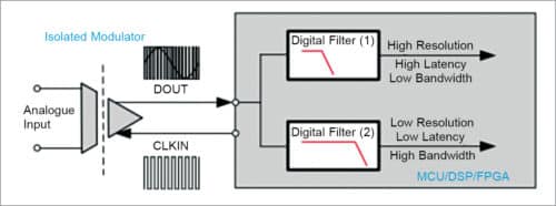
Additionally, as shown in Fig. 3, multiple digital filters can be implemented in parallel to achieve higher sample resolution, lower latency, and higher bandwidth, all at the same time. One of the digital filters can implement a high OSR digital filter for better noise performance, and another one can implement a low latency digital filter.
With the system advantages offered by an isolated modulator-based solution, there is a resulting trend to move to an isolated modulator-based solution in high-performance systems.
Isolated modulators in traction inverters
Fig. 4 shows an implementation of an isolated modulator-based solution in automotive traction inverters.
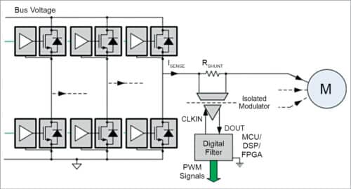
Traction inverters have a direct influence on the driving experience and require precise control of speed and torque of the traction motor. A shunt coupled with an isolated delta-sigma modulator provides the highest-quality feedback signals to the controller in order to establish the pulse-width modulation (PWM) pattern for bridge transistors. The digital filter implementation allows the engineer to tune the quality of traction motor controls.
As shown in Fig. 3, FPGA, MCU, and DSP can have multiple digital filters running in parallel. One of the digital filters can be a high-performance digital filter that provides accurate feedback signals to control the bridge transistors. Another digital filter can be a low-latency digital filter for detecting overload or overcurrent conditions. A third-order (Sinc3) filter with a different OSR can be used for both digital filters.
Table 3 lists the recommended devices for use with the isolated amplifiers and modulators.
Conclusion.

Isolated modulators offer higher sample resolution and accuracy compared to isolated amplifiers. With the combination of isolated modulators and custom digital filters, engineers can trade system latency and bandwidth with sample resolution. Isolated modulator-based solutions require fewer components and enable a smaller solution size at a reasonable cost. Isolated modulators are strongly recommended in isolated measurement applications wherein high sample resolution or low latency is required.
Krunal Maniar works as the business development manager at Texas Instruments, Dallas, USA


