In the previous parts we covered multi-layer PCB designing. Now, let us look at grounding or earthing.
Grounding can be defined as a connection, whether intentional or accidental, between an electrical circuit or equipment and earth or to some conducting body that serves in place of earth. Hence, one can conclude that grounding is nothing but connection to earth or to a conductor that serves as earth. Going by this definition, a connection between a circuit and its 0V reference can also be considered as grounding, while earthing can be considered as a case of grounding where the ground is essentially planet Earth.
Purpose of grounding or earthing
The primary aim of grounding is to prevent shock hazard that exists in a high-voltage distribution system. Other functions include power fault clear-out, protection against lightning and electrostatic discharge (ESD) hazards and protection against electromagnetic interference (EMI).

Preventing shock hazard. Shock hazard exists when equipment enclosure/chassis, by virtue of a fault or otherwise, is not connected to ground. If a live wire is accidentally connected to the chassis, then the latter becomes live. Now, if you happen to touch it, current will get a path to ground through your body. If the chassis is connected to ground, say, by a low-resistance wire, fault current would prefer to flow through this low-resistance path rather than your body. This current triggers a fuse or circuit breaker, alerting you. Even if you ignore this warning, the frame will be at ground potential and there will be no danger of a shock.
Power fault clear-out. Aging, insulation damage, environmental contaminants in insulation and so on can cause breakdown in insulation during a fault, resulting in arcing that can lead to fire. When the neutral terminal of power supply is connected to earth, any fault in grounding would show up as a phase-to-neutral short and would trip the fuse, arresting the hazardous voltage.

Protection against lightning hazard. Grounding is essential for draining severe lightning currents (30kA to 100kA) to ground, which otherwise can be life-threatening and can also damage electronic components in an equipment.
Electrostatic drainage. Static charge accumulated on the human body and other objects can damage fragile electronic components by discharging through these. Proper grounding in equipment can bypass the path of this discharge current, taking it away from sensitive components. Proper grounding in facilities can reduce damage to sensitive components during manufacturing and handling, too.
EMI control. Grounding/earthing is necessary in EMI control. Shields need to be connected to ground/earth as EMI currents induced in the shield need a path to dissipate to ground. Filters used to reduce conductively-coupled common-mode currents can be effective only if connected to ground to provide a drain for EMI currents. Also, ESD and its associated transient noise is reduced by bonding and earthing equipment frames.
Equipment and system grounding
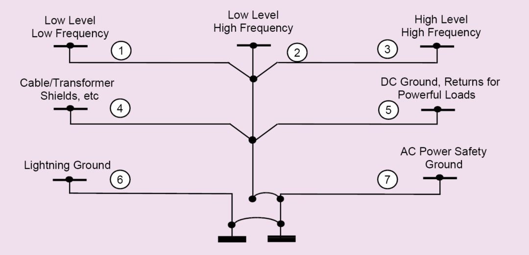
Grounding/earthing hierarchy for a typical installation is shown in Fig. 18. The method of grounding and the type and material of the grounding conductor depend upon the position of the ground in the grounding hierarchy.
At the top of grounding hierarchy (point 1 in Fig. 18) are the low-level low-frequency grounds for circuits that work up to a few kilohertz like audio circuits. A simple wire can be used for such grounds since metals behave as pure resistance at these frequencies.
For low-level high-frequency digital signals up to tens of megahertz (point 2 in Fig. 18), a mesh has to be used for grounding (for example, a bond strap made of wire mesh) since metals start to exhibit inductive properties and meshes are good at providing a low inductance.
For high-level high-frequency EMI currents (which have spectral components up to hundreds of megahertz), grounding has to be done via flat metal strips to a ground plane (point 3 in Fig. 18). This is because metals become highly inductive, and only metal planes and sheets can provide low enough impedance at such high frequencies.
Next in the hierarchy are grounds for cables and transformer shields and those for DC returns of power loads (points 4 and 5 in Fig. 18). Return currents from these should not affect the returns above these in the hierarchy.
Lightning and AC power-safety grounds are at the bottom of the hierarchy, and these should also be distinct from one another. Lightning grounds carry hundreds of amperes of current and, hence, the need to separate such grounds from AC power grounds.
Types of grounding
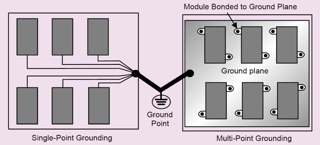
Single-point grounding. Here, each subsystem/module has its own ground. These individual grounds are connected by the shortest route to a single system ground point by simple wires. Such a system is advantageous for low-frequency and analog circuits because no common impedances exist.
At high frequencies (above 1MHz), however, grounding wires start to exhibit high inductance and, consequently, start offering high impedance to ground currents. At the same time, capacitive reactance of stray capacitance between the modules starts reducing. Ground currents no longer follow the high-impedance path offered by ground wires to ground, but are rather invited to follow the low impedance offered by the parasitic capacitance to other modules. This causes common-mode coupling, which can be reduced by reducing the inductive reactance of the ground wires. This is achieved by multi-point grounding.
Multi-point grounding. In multi-point grounding (Fig. 19), each subsystem/module is bonded as directly as possible to a common low-impedance equi-potential ground plane (essentially a continuous sheet of metal). A metal sheet offers far less impedance at high frequencies (above 1MHz) compared to wires. This is because sheets have more surface area, which reduces resistance to high-frequency currents that tend to flow on the surface due to skin effect.
The sheet also provides multiple parallel paths for ground currents, which reduce inductance. In such a scenario (when modules are mounted on a ground plane), ground currents are invited to follow the low impedance of the ground plane to ground, rather than going to another module.
Hybrid grounding. Hybrid grounding is used in situations where systems involve both high-frequency (digital) circuits and low-frequency (analogue) circuits.
Reducing ground impedance coupling
Due to improper grounding and bonding, or due to improper grounding practices, ground impedance tends to increase. This is shown as lumped impedance in the Fig. 20 (a).
EMI currents flowing through this impedance cause voltage drop Vcm across it, which forces common-mode EMI currents I1 and I2 through the circuit. The first way is to eliminate this common impedance completely by grounding the modules at a single point as shown in Fig. 20 (b).
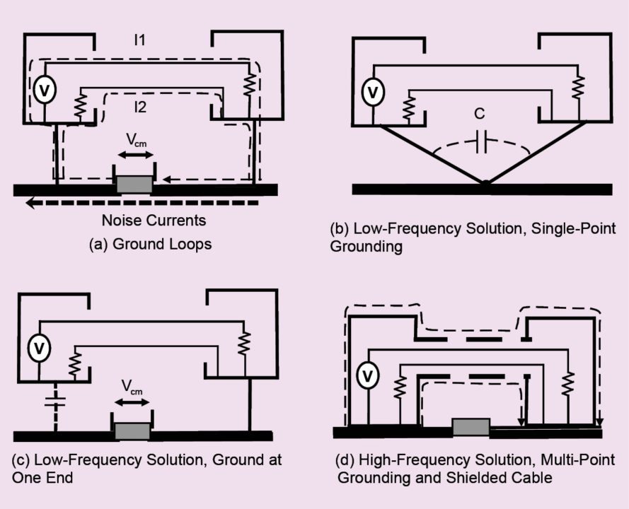
The second option is to open the ground loop by grounding only one of the modules as shown in Fig. 20 (c). But these hold good only at low frequencies up to a few tens of kilohertz, where this impedance behaves only as resistance.
At higher frequencies, stray capacitance (shown as dotted lines) begins to appear between grounding cables or between the module and the ground, causing common-mode currents to circulate again.
Also, at higher frequencies, ground wires themselves start offering high impedance since their inductive reactance and resistance due to skin effect start to increase, causing potential gradients along the wire.
Therefore at high frequencies, efforts should be directed towards reducing ground impedance, which, in turn, can be reduced first by reducing inductance, that is, replacing the wires by a metal sheet (a mounting plate) and then to reduce the value of ground resistance by proper bonding practices.
Also, interconnecting cables should be shielded so that common-mode EMI currents now flow as shown in Fig. 20 (d) on the outside of the shield, reducing common-mode coupling.
This article is an extract from a book by the author. The next part will cover bonding.
For reading more design guides like this: click here
Chetan Kathalay is working as scientist in Electronics Test and Development Centre, Pune. He is BE in electronics from Nagpur University