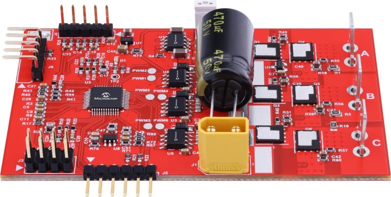
A brushless DC (BLDC) motor driver for power tools that claim to meet the demands of modern motor control applications.

A brushless DC (BLDC) motor driver is necessary for power tools as it controls the motor’s speed, direction, and torque. It receives signals from a controller or a user and converts them into the appropriate output signals to drive the motor. BLDC motors are becoming increasingly popular in power tools due to their high efficiency, reliability, and long lifespan compared to traditional brushed motors. To simplify the design process, Microchip has launched a reference design of the BLDC motor driver for power tools that aims to streamline the design process. The driver claimed to be designed for high-performance, cost-effective motor control applications, specifically those found in power tools such as drill machines, disc cutters, circular saws, leaf blowers, and more. The Reference Design can power Brushless DC/permanent magnet synchronous motor (BLDC/PMSM) motors with a peak power of 800W and RMS phase currents of up to 50A. It can operate with input voltages ranging from 12.5V to 28V, making it suitable for applications powered by battery strings of up to 6S (Li-Ion cells).
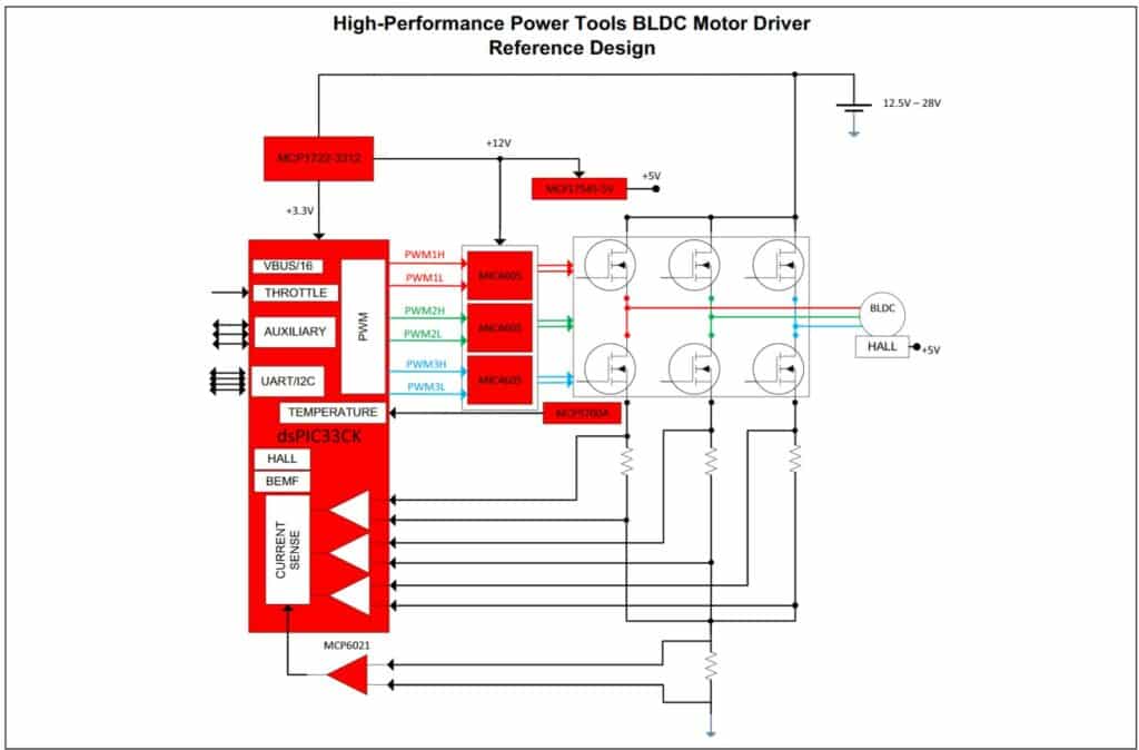
The reference design is based on dsPIC33CK high-performance Digital Signal Controller (DSC). This design showcases the potential of the DSC when used in conjunction with the half-bridge metal oxide semiconductor field effect transistor (MOSFET) driver family for controlling power tools. Six high-performance MOSFET transistors with low drain-to-source resistance have been utilized to implement a three-phase inverter capable of handling high-phase currents with minimal conduction losses. To drive these MOSFETs, the MIC4605 MOSFET drivers have been employed. Additionally, an MCP9700A temperature sensor has been incorporated to monitor the temperature of these power MOSFETs, protecting against overheating.

The BLDC motor driver design features a pulse width modulation (PWM) switching frequency range of 12kHz to 50kHz. The design supports sensored/sensorless motor control algorithms and onboard temperature measurement. The brushless DC motor driver for power tools reference design is a comprehensive standalone motor controller designed for use with PMSM/BLDC in power tools. The board can drive a three-phase brushless DC motor with a continuous 15A RMS (root mean square) phase current, rated for a voltage range between 12.5V and 28V. The design is well-equipped with both hardware and software. Still, users can modify or fine-tune the provided firmware using a PicKIT4 and MPLAB X IDE (integrated development environment) in-Circuit debugger/programmer.
This reference design has been tested by Microchip. It comes with Bill of Material (BOM), schematics, Printed circuit board (PCB) layout, etc. You can find additional data about the reference design on the company’s website. To read more about this reference design, click here.


