With recent advancements in communication technology, there is a new technique—called ambient backscatter—that allows devices to communicate with each other, for which it does not require batteries. Let us take a glimpse at what ambient backscatter is.
Ambient backscatter is a new type of wireless communication that uses ambient signals in radio frequency (RF) range to enable communication between devices and powering these without using batteries. This system utilises existing ambient RF radiations as the source of power and for communication between devices. It makes use of ambient RF signals such as TV broadcast signals, mobile communication signals, Wi-Fi and so on. For all such applications, ambient backscatter does not require a separate power source to operate.
An ambient backscatter device communicates by absorbing and reflecting RF signals. In a backscatter communication system, a device communicates by modulating the reflection of incident RF signals (instead of generating RF signals). Hence, communication using this technique is more energy efficient than conventional radio communication.
How it works
The working of ambient backscatter communication can be understood by the following example. Consider two nearby battery-free devices (A and B) and a TV tower as source of ambient RF signals in a certain area with good signal strength, as shown in Fig. 1. Suppose, A wants to send a message to B. To do so, A backscatters ambient signals to convey the message in the form of bits—it can be indicated by switching the device’s antenna between reflecting and non-reflecting states corresponding to either bit 0 or 1.
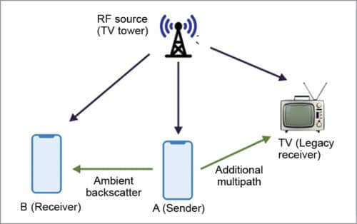
Signals that are reflected by A create an additional path from the TV tower to B. On the other hand, B detects the change in signals caused by backscattering and decodes A’s message using some decoder logic.
General architecture of ambient backscatter
The basic design of ambient backscatter consists of mainly three parts: harvester, transmitter and receiver (Fig. 2). Harvester is the circuitry responsible for the extraction of energy from ambient RF signals to provide power to the battery-free device.
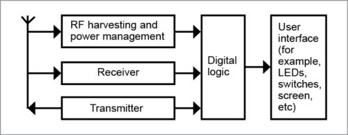
Transmitter conveys the message by backscattering RF signals that are incident on its antenna by modulating the antenna to reflect or absorb signals.
On the receiver, an antenna intercepts some of the power of RF signals backscattered by the transmitter. Finally, the message is decoded by using a decoding technique.
RF energy harvester
An RF energy harvester module consists of an antenna that receives ambient RF signals. Received signals are amplified by voltage doubler/multiplier, which does not require any power source for its operation. For larger amplification, the voltage amplifier is formed by cascading a number of voltage doublers in series (Fig. 3).
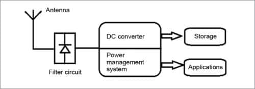
A DC converter—a rectifier for RF signals—converts the received small voltage of RF signals and stores harvested energy in a capacitor. The harvester also has a power management system that takes care of utilisation of stored power, which can later be utilised for different applications.
Ambient backscatter transmitter
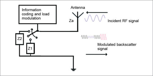
Backscattering of RF signals is based on the basic principle of reflection and absorption of electromagnetic waves. When an electromagnetic wave encounters a boundary between two transmission media that have different impedances/densities, it is reflected or absorbed. Thus, backscattering of RF signals is achieved by modulating the impedance of an antenna in the presence of an incident signal.
The backscatter transmitter includes a switch (load modulator) that modulates impedance of the antenna and causes a change in the amount of energy reflected by the antenna (Fig. 4). Input signals of the switch are a sequence of bits 1 and 0, which the switch uses to toggle the antenna between backscatter (reflective) and non-backscatter (absorptive) states to send bits to the receiver. Reflective state represents bit 1, and absorptive state represents bit 0.
Ambient backscatter receiver
To demodulate from backscatter signals, the receiver adopts a simple circuit composed of three main components: envelope averager, threshold calculator and comparator (Fig. 5). Received signal is first smoothened to average out the variations due to modulation.
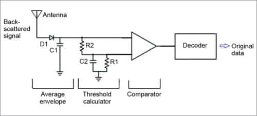
Next, the threshold calculator computes a threshold by taking the mean of the two voltage levels.
Then, by comparing instantaneously generated voltage at the first step with the threshold, it interprets the received signals into a stream of information bits.
The ambient backscatter receiver is implemented using an envelope detector and resistive/capacitive (RC) circuit to smoothen out natural variations in RF signals (TV signals). Output of the averaging circuit produces two signal levels (say, V1 and V0; V1>V0), corresponding to bits 1 and 0.
To distinguish between the two, the receiver first computes a threshold value using threshold computation circuitry. The produced signal level along with threshold value is given to the comparator, which then produces bits 1 and 0 corresponding to V1 and V0. Output of the comparator is then passed to the microcontroller for decoding and further processing. Averaging mechanism is used for decoding the received signal.
Designing ambient backscatter
Designing of ambient backscatter is challenging due to the following reasons.
First, it uses uncontrollable RF signals that already have information encoded in these. Hence, it requires a different mechanism to extract backscattered information.
Second, a general backscatter receiver uses power consuming components such as oscillators and analogue-to-digital converters (ADCs) and decodes the signals with relatively complex digital signal processing techniques. These techniques are not practical for use in a battery-free receiver.
Last, ambient backscatter does not have a centralised controller to coordinate all communication. For this, the designer needs to develop its own protocol for information transmission and reception.
Advantages
There are several advantages of ambient backscatter.
- It is battery-free. While it can only collect microwatts of electricity, it is enough to power itself and small onboard sensors such as LEDs, touch sensors, low power displays and the like.
- It does not need any special purpose chips and other analogue components. It can be manufactured using commonly available components.
- Its size is relatively small—about the size of a carrom coin.
- Cost of manufacturing is quite low—about ₹ 50 each.
- It does not need a dedicated power source (unlike in RFID communication), since it leverages radio signals that are already around.
Limitations
Ambient backscatter technology has certain limitations.
- As backscatter transmitters use ambient RF signals for circuit operation and data transmission, it is usually not possible to control RF sources for transmitting power and operating on certain frequencies.
- Ambient backscatter communicates ranging from several metres to tens of metres with low data rates. While it depends on scenarios where the technology is applied, if it needs to cover a large area, multiple devices are required.
- The amount of electricity it collects is small. It can only collect enough electricity to power small sensors like LEDs, pressure sensors, accelerometers and so on. It can be faded due to noise.
- Ambient backscatter may potentially face several security issues since backscatter transmitters are simple devices and RF sources are not controllable.
Applications
Development of ambient backscatter technology enables a method for device-to-device communication. It can be used for connecting the Internet of Things (IoT), which is the future of connected living. For example, a table could use this technology to alert someone who was around it and left a key on the table.
Smart sensors could be built, placed permanently inside any structure and set to communicate with each other to notify about the structure’s condition.
Ambient backscatter can be adopted in many applications such as smart devices (wearables like health trackers to perform continuous analysis of a person’s health condition), in logistics for tracking and medical equipment to monitor patient health even when there is no electricity and so on. This technology allows devices, that is, backscatter transmitters, to operate independently with minimum human intervention.
Some prototypes developed using this technology are: a smart card to process payments to another backscatter device used as a bus pass and a credit card-sized tracker used to track items and alert users when an item is misplaced.
In a nutshell
Ambient backscatter is a new communication technology that uses ambient RF signals to power devices and for communication. This technique does not require a dedicated power source—it does not generate its own RF signals. Due to this reason, it is more energy efficient than any conventional wireless communication.
In designing ambient backscatter, challenges relating to powering devices, controlling RF signals and protocols for transmission and reception were faced. Despite these, it proves to be a self-sustainable, low-cost communication system. This new battery-less communication system can revolutionise the world of low-power embedded devices and take a step towards the IoT.
Dr Rajiv Kumar Singh holds a PhD in electronics engineering from IIT (BHU), Varanasi, and is currently employed with Institute of Engineering & Technology (IET), Lucknow as assistant professor. He has received senior research fellowship of UGC at Centre of Advanced Study at IIT, Varanasi. His interests include wired and wireless technologies for high-speed Internet access
Chandan Kumar Maurya is pursuing BTech in electronics and instrumentation engineering from IET, Lucknow


Crystals, as in Crystal radios played with by many of us when children. Could this provide the power needed?
Kevin. Explain more what you mean.