


 This emergency photo lamp can be powered either by a rechargeable battery (like 3.6V Ni-Cd) or a non-rechargeable battery (3.0V CR2032). The white LED (LED1) glows automatically when the power fails and you are left in dark. The quiescent current of the circuit is very low and the battery is practically used only when the LED glows.
Emergency photo lamp circuit
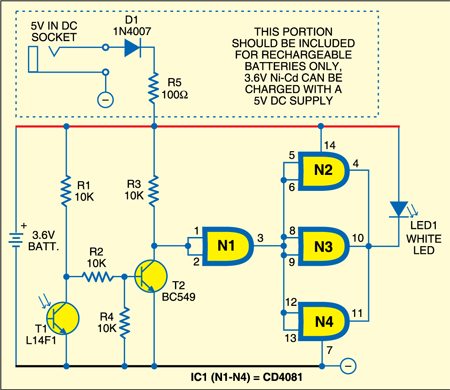
Above is the circuit of the emergency photo lamp. When light falls on phototransistor T1 (L14F1), it conducts and transistor T2 does not conduct, making the output of gate N1 high. As gates N2, N3 and N4 are connected to the output of gate N1, their outputs also remain high. As a result, the white LED does not glow. An additional circuit for 5V DC socket is shown within the dotted lines for charging the rechargeable battery.
In the dark, when the light does not fall on phototransistor T1, it does not conduct and transistor T2 conducts, making the output of gate N1 low. As a result, the outputs of gates N2, N3 and N4 also remain low and the white LED glows.

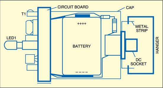
Construction & testing
Assemble the circuit on a small general-purpose PCB and fit it (including the battery) inside the cap of a glue stick tube with the LED facing down (see Fig. 2). Hang it suitably at your workplace, say, in the office or kitchen, such that the ambient light falls directly on the phototransistor.
The project was first published in May 2010 and has recently been updated.
