


 In this project, a MATLAB platform to control up to four electrical equipment is presented. Controlling electrical equipment from a remote location using a control panel is employed in many applications. An important application is in a process plant where an operator in a control room, sitting in front of a computer terminal and running a human-machine interface (HMI) application program for process monitoring and controlling, can effectively send hard, real-time control commands/signals to multiple actuators present on the field. A graphical user interface (GUI)-based HMI application enhances the user-friendliness of such an approach.
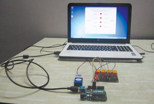
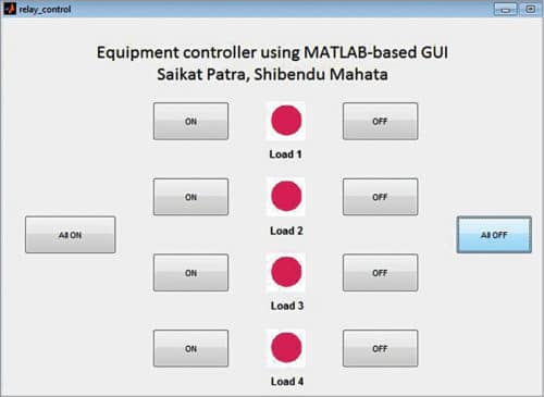
The authors’ prototype and the MATLAB-based GUI front panel are shown in Figs 1 and 2, respectively.
Circuit and working
Components used for this project are described below.

Arduino Uno board
Arduino Uno is an AVR ATmega328P microcontroller (MCU)-based development board with six analogue input pins and 14 digital I/O pins. The MCU has 32kB ISP flash memory, 2kB RAM and 1kB EEPROM. The board provides the capability of serial communication via UART, SPI and I2C. The MCU can operate at a clock frequency of 16MHz. In this project, digital I/O pins 9, 10, 11 and 12 of Arduino are configured as output pins.
SPDT relay
A relay is an electromechanical switch. Relays used here are of single-pole, double-throw (SPDT) type. In this type of relay, output side has three terminals: normally-open (NO), normally-closed (NC) and common (C).
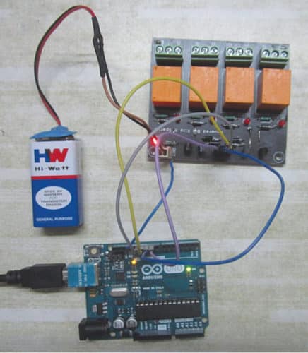
When the relays are not energised, NC and C terminals are short-circuited, and NO and C terminals are open-circuited. When relay coil is energised, NC and C terminals are open-circuited, and NO and C terminals are short-circuited. The prototype of the relay board is shown in Fig. 3.
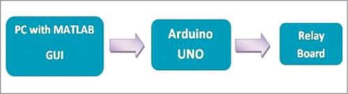
Block and circuit diagrams for controlling the relays are shown in Figs 4 and 5, respectively.
In this project, when you click on a particular pushbutton in the GUI, MATLAB program executes a callback function corresponding to that pushbutton in relay_control.m MATLAB program. Within that function, instructions to set/reset digital I/O pins 9, 10, 11 and 12 of Arduino are executed to drive the relay as desired.
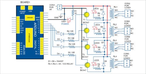
When a particular digital I/O pin is set high by clicking on the corresponding pushbutton using a mouse, the corresponding relay is energised. Four BC547 bipolar junction transistors (T1-T4) are additionally used as drivers because digital pins of Arduino cannot directly source sufficient current to energise the relays.
Diodes D1 through D4 are used as protection diodes to prevent the sinking of current into Arduino digital pins. D5 through D8 are fly-back diodes that are used to prevent damage to electronic components due to back electromagnetic force (EMF) produced by inductive action of the coils of the relays.
LED1 shows power-on status of the circuit, whereas LED2 through LED5 are used as indicators to show status of the four relays (RL-RL4). Power to the relay board is provided separately from a +9V battery.
Software
1. Arduino IDE is used for programming Arduino Uno. The latest IDE can be downloaded for free from Arduino’s official website. After downloading Arduino IDE, install it. Note the directory of Arduino IDE installation.
2. Download Legacy MATLAB and Simulink Support for Arduino package from MathWorks website. Extract the compressed folder named ArduinoIO. From ArduinoIO folder, copy pde folder and paste it in C:\Program Files (or Program files x86)\Arduino\libraries. (Path may be different depending on the installation directory of the IDE.)
After pasting pde folder in the correct location, open Arduino IDE. If you have pasted the folder in the correct location, you will find pde in FileExamplespde. Open the code from FileExamplespdeadioes.
3. Connect Arduino Uno board to the PC. From Device Manager, note the COM port at which Arduino Uno is installed. From Tools in Arduino IDE, select the board as Arduino Uno and select the COM port number noted earlier. Upload adioes code to Arduino Uno by clicking Upload in the IDE.
4. Copy the entire contents of the extracted ArduinoIO folder to a folder in My Documents (for Windows PC).
5. Our GUI application program has been developed in R2014a version of MATLAB. After installing this version of MATLAB on the PC, open install_arduino.m file present in the directory where you have copied the contents of ArduinoIO folder. Now, run install_arduino.m file. This code should install correctly and save the path of Arduino support package.
6. Open the source code file for this project, titled relay_control.m. Edit a=arduino (‘COM9’) line with the COM port number in the PC where Arduino Uno has been installed.
After running the project file, MATLAB will try to communicate with the board. After successful communication is established, you will be able to control the equipment by clicking on the appropriate pushbutton in the GUI.
Construction and testing
A PCB layout of the equipment controller circuit is shown in Fig. 6 and its components layout in Fig. 7.

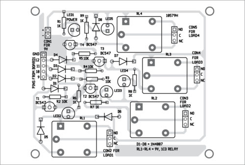
Download PCB and Component Layout PDFs: Click here
After uploading Arduino code into Board1 as explained earlier, run MATLAB GUI program. Connect 9V battery to the circuit. LED1 glows to indicate the presence of power in the circuit. From GUI program, click on On/Off button to switch on/off the corresponding electrical device. The on status of the devices is indicated by the glowing of LED2 through LED5. That is, if On button corresponding to Load1 is clicked, RL1 will get energised and load connected at CON2 will get turned on. If Off button is clicked, RL1 will get de-energised and Load1 will be turned off.
Download source folder here: Click here
Saikat Patra is passionate about electronics and MCU-based embedded system applications
Shibendu Mahata is an M.Tech (gold medallist) in instrumentation and electronics engineering from Jadavpur University. He has a keen interest in MCU-based real-time embedded signal processing and process control systems

Dear sir can we change the state of digital output in arduino means without help of program. Like any input key so that we can chnahe output low or high as per reqiurement
sir, this PCB design can be replaced by a relay module or not?
Yes, the given PCB is basically the relay driver section and so you can replace it with a 4-channel relay module readily available in the market.