


Connecting to a wireless LAN network is a popular option for accessing internet-based applications. A readily available alternative is tethering or using a mobile hotspot, which allows the sharing of a smartphone’s mobile data to connect other devices to the internet.
Most Android smartphones offer the capability to share mobile data through Wi-Fi, Bluetooth, or USB. Tethering effectively transforms a smartphone into a Wi-Fi access point, providing connectivity for laptops, tablets, microcontrollers, and low-power systems-on-chips (SoCs).
In areas with cellular network coverage, tethering offers the advantage of internet access from virtually anywhere, eliminating the need for separate data plans for each device. When password protection is enabled, tethering also ensures a cost-effective and secure internet connection across multiple devices.

However, this method can significantly drain the smartphone’s battery, leading to more frequent recharging, which may reduce the convenience and flexibility typically associated with tethering.
POC Video Tutorial in English
POC Video Tutorial in Hindi
To address the issue of rapid battery discharge during tethering, a setup utilising an ESP32 development board controlled via the ESP RainMaker app is proposed. This configuration includes four parallel systems, each operating on a separate SoC, to collect data and manage various functions during testing.

To ensure continuous 24/7 connectivity, the smartphone serving as the mobile hotspot or tethering unit was physically recharged at specific intervals.
A critical aspect of this setup is establishing a node through the ESP RainMaker app, which mitigates the problem of faster battery depletion in the tethering smartphone. Fig. 1 shows the authors’ prototype.
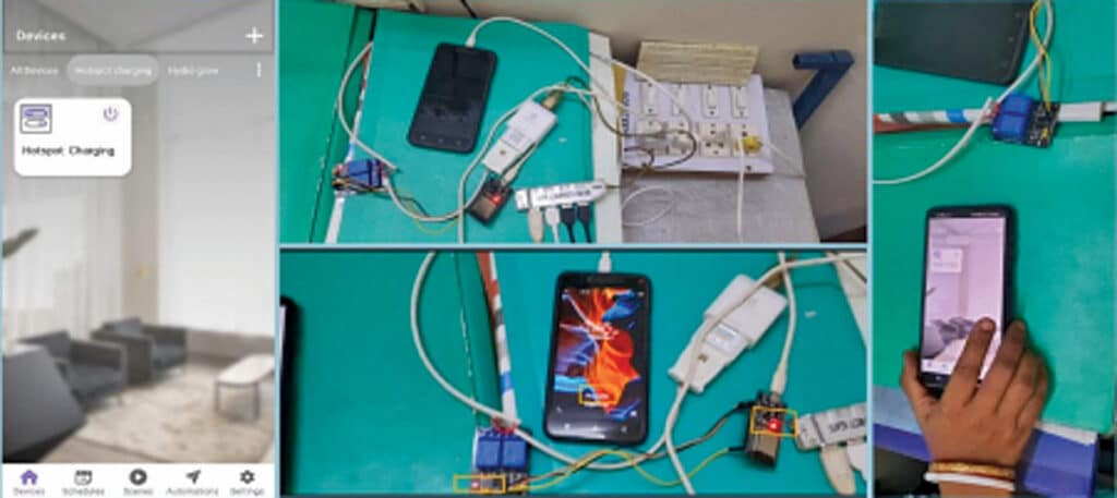
Fig. 1 showcases the prototype, highlighting the relay module LED, ESP32 development board, and the charging display on the smartphone when the setup is in the ON mode. Fig. 2 provides a block diagram representation of the proposed setup. The components required to build this setup are detailed in Table 1.


Hi, the source code is present at the end of the article or you can download from here: https://www.electronicsforu.com/wp-contents/uploads/2024/08/mobilethetring.zip