
Extraction of centre of mass of a binary pattern is an important task in pattern recognition area in digital image processing domain. The pattern’s shape and size can be estimated using the radii profile that is computed around the centre of mass. The centre of mass of a binary pattern is computed using the first order moments of the pattern pixel’s Cartesian Coordinates. For all, very firstly the pattern is converted to a binary class i.e. pattern as in black on a white color background or vice versa. Black and white colors are attributed as 0 and 1 respectively (binary form) in digital image processing.
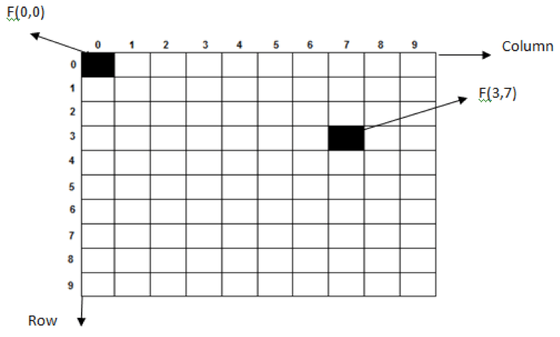
In matlab IDE, the image dimensions are taken as row x column. The pixel at (0,0) location is at top left corner of the image (refer to figure-1). An example pixel at location (3,7) is shown as F(3,7).
A grey color pattern of size 7×5 is shown in figure-2. It is converted to binary pattern as shown in figure-3. The grey pattern can be binarized using the Otsu algorithm. The equivalent binary pattern is shown in figure-3.

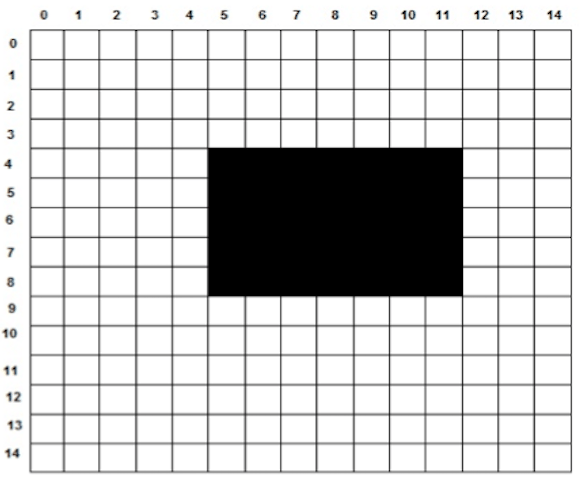
The binary image pattern (figure-3) is scanned from left to right and top to bottom i.e. in row x column manner. This is also called as raster scan. This task is performed by using the imread() function in matlab. The imread() function enables to have the binary image pattern in row x column matrix of ‘0’ and ‘1’ as black and white pixels. The matrix size is (row x column) i.e. 15×15 as in figure-3.
The centre of mass of the pattern under test is computed using the first order moments of the Cartesian coordinates of the pattern’s pixels i.e. the pixels with black in color or the matrix elements with zero value. The first order moments are computed by using the following equations:

Where (RCoM, CCoM) are the row and column coordinate of the centre of mass of the pattern under test.
(Ri, Ci) are the ith pixel coordinate of the pattern i.e. matrix elements with zero value, and,
‘N’ is the total no. of pixels on pattern body i.e. no. of matrix elements with zero value.
From figure-3, the centre of mass is given by the followings:
RCoM = (4+5+6+7+8+4+5+6+7+8+4+5+6+7+8+4+5+6+7+8+4+5+6+7+8+4+5+6+7+8+ 4+5+6+7+8) / 35 = 210/35 = 6
CCoM =(5+6+7+8+9+10+11+5+6+7+8+9+10+11+5+6+7+8+9+10+11+5+6+7+8+9+10+11+5+6+7+8+9+10+11)/ 35 = 280/35 = 8
Here, N = 35 (Total No. of pixels on pattern body.
Therefore, (RCoM, CCoM) = (6, 8)
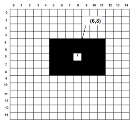
The centre of mass for the test pattern (figure-3) comes out to be at location (6,8) and marked as white in figure-4 given below.
Using the centre of mass, the pattern’s shape and size can be estimated by computing radii profile.
The working code for the CoM using matlab is given in below text box.
Code for CoM Extraction
close all,
clear all,
clc,
ProjectPath = pwd;
PatternPath = strcat(ProjectPath,’\Pattern_3.jpg’);
Orig = imread(PatternPath);
Gray = rgb2gray(Orig);
Threshold = graythresh(Gray);
BinaryPattern = im2bw(Gray,Threshold);
subplot(1,2,1);
imshow(BinaryPattern);
title(‘Binary Pattern’);
[row col] = size(BinaryPattern);
Row_CoM=0;
Col_CoM=0;
Count=0;
for r=1:row
for c=1:col
if(~BinaryPattern(r,c)),
Row_CoM = Row_CoM + r;
Col_CoM = Col_CoM + c;
Count = Count+1;
end
end
end
Row_CoM = Row_CoM/Count;
Col_CoM = Col_CoM/Count;
subplot(1,2,2);
imshow(BinaryPattern);
title(‘Binary Pattern with CoM’);
j = imline(gca,[Col_CoM Col_CoM],
[Row_CoM-10 Row_CoM+10]);
j = imline(gca,[Col_CoM-10 Col_CoM+10],
[Row_CoM Row_CoM]);
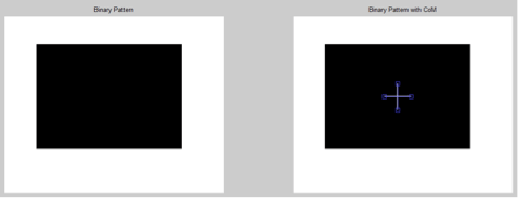
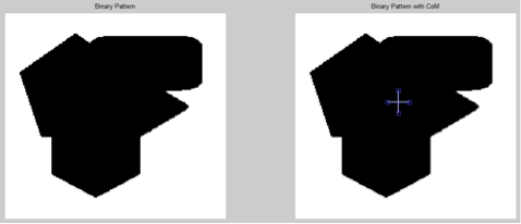
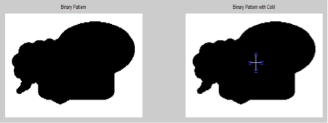
Snap shots of CoM Extraction


Can you please explain the program code, step by step