


 Fastest finger first technique is used in quiz shows (with rapid fire rounds) to find the order in which participants press the buzzer (to give an answer to the question). This project is designed for four players. For real-time applications, calling-bell switches can be used over tactile switches.
Circuit and working
Circuit diagram of the microcontroller (MCU)-based fastest finger first is shown in Fig. 1. It is built around 8-bit microcontroller AT89S51 (IC2), 230V AC primary to 9V, 300mA secondary step-down transformer (X1), 16×2 LCD (LCD1), 5V voltage regulator IC 7805 (IC1) and a few other components.
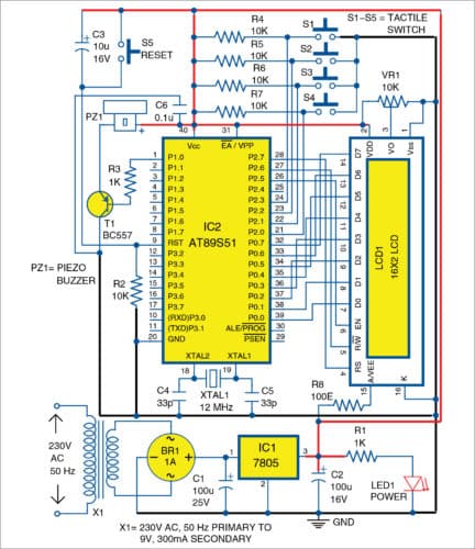
The power supply circuit is designed to provide +5V regulated DC voltage for the MCU and LCD1. Bridge rectifier (BR1) is used to convert 9V AC to 9V DC. IC1 regulates input DC voltage to provide +5V DC. Capacitors C1 and C2 act as filters to remove noise from the power supply. LED1 is used as power supply indicator and resistor R1 limits the current flowing through LED1.

The oscillator section—comprising 12MHz crystal (XTAL1), capacitor C4 and C5—is used to provide clock pulse to the MCU. Resistor R2 and capacitor C3 form the power-on reset circuitry to reset the MCU whenever the supply is switched on. Switch S5 is used to manually reset the MCU for fresh operation. Transistor T1 is used as the driver for peizo buzzer PZ1, and resistor R3 limits the base current of T1. PZ1 is used to provide a beep sound whenever a quiz cycle begins or ends. The buzzer is turned on when logic 0 is present in I/O pin P1.0 of IC2.
S1 through S4 are input switches for four players named A, B, C and D, respectively. Resistors R4 through R7 are used as pull-up resistors for switches S1 through S4, respectively.
Whenever a switch is pressed, logic 0 is given as input to the respective input pin. And, LCD1 displays the corresponding name of the user. Preset VR1 is used to control the contrast voltage for LCD1, while resistor R8 limits the current flow to LED backlight of LCD1.
Whenever the circuit is switched on, or reset switch S5 is pressed, the device starts its operation with a beep sound and displays “fastest finger first” message in the first line of LCD1. Then, LCD1 shows “1 2 3 4” in the first line and waits until the user presses a switch.
Whenever a switch is pressed, the corresponding name is displayed in the second line of LCD1. The names appear in the sequence their switches are pressed. After the last (fourth) switch is pressed, “!Press! !Reset!” message is displayed on LCD1 followed by a beep sound. The cycle can be started again by pressing S5.

Software
The program is written in embedded C language using Keil software. The code also works on other 8051 (89C51, 89C52, 89S51, etc) compatible MCUs. The compiled hex file can be burned into the MCU using any suitable programmer. At EFY Lab, USB 8051 programmer was used to burn the hex code.
Download source code
Construction and testing
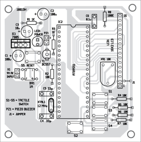
An actual-size PCB layout for the MCU-based fastest finger first is shown in Fig. 2 and its components layout in Fig. 3. Assemble the project as per the circuit diagram. Burn the given hex file into the MCU. Power on the circuit, and the LCD will display “fastest finger first” message. If the text is not visible, adjust VR1 till the text is clearly visible.
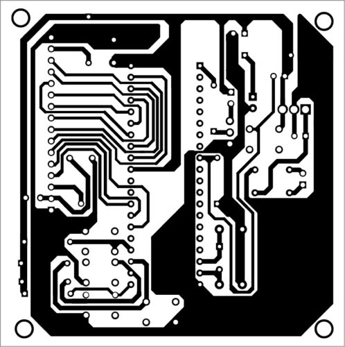
Download PCB and component layout PDFs: click here
K.J. Kumaresh is an electronics circuit designer
Thanks a lot dear