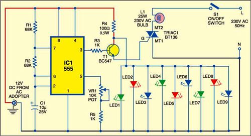
 Here is the circuit for a portable electric lamp-cum-LED flasher. It uses a 25W, 230V AC bulb and nine LEDs. When the bulb glows all the LEDs remain ‘off, ‘and when the LEDs glow the bulb remains ‘off.’
The circuit is built around timer IC 555 (IC1), which is wired as an astable multi vibrator generating square wave. The output of IC1 drives transistor T1.
Working of the circuit is simple. When output pin 3 of IC1 goes high, transistor T1 conducts to fire triac1 and the bulb glows. Bulb L1 turns off when output pin 3 of IC1 goes low.
The collector of transistor T1 is connected to anodes of all the LEDs (LED1 through LED9). So when T1 is cut-off the LEDs glow, and when T1 conducts the LEDs go off. Current-limiting resistor R4 protects the LEDs from higher currents.
In brief, the bulb and the LEDs flash alternately depending on the frequency of IC1. Flashing rates of the bulb as well as LEDs can be varied by adjusting potmeter VR1. Connect the power supply line (L) of mains to bulb L1 via switch S1 and neutral (N) to MT1 terminal of triac1.
A 12V, 200mA AC adaptor is used to power the circuit. Using switch S1,you can switch off the bulb permanently if you do not want it to flash.
Assemble the circuit on a general-purpose PCB and enclose in a circular plastic cabinet keeping the bulb at the centre and LEDs at the circumference. Drill holes for mounting the ‘on’ /’off’ Switch .Use a bulb holder for bulb L1 and LED holders for the LEDs. Also use an IC socket for timer IC 555.
Warning. While assembling, testing or repairing, take care to avoid the lethal electric shock.


