


These power supplies are particularly valuable in applications requiring multiple output voltages, high-voltage isolation, and compact design.
Flyback-isolated power supplies are critical components in modern electronics, known for their efficiency, versatility, and ability to provide reliable isolation between input and output. The isolation ensures safety by protecting sensitive electronic components and users from high-voltage spikes and noise. Additionally, flyback topology is favored for its cost-effectiveness and simplicity in design, making it a preferred choice for a wide range of devices, from consumer electronics to industrial equipment. Their ability to maintain high efficiency and stability across various load conditions further underscores their importance in ensuring the reliable operation of complex electronic systems.
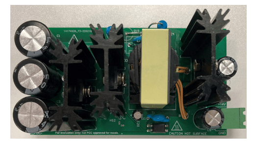
This reference design PMP41009 by Texas Instruments offers an isolated +14-V, 56-W output using a quasi-resonant flyback topology, capable of operating from a DC input range of 350-V to 1000-V. At the core of this design are cascode MOSFETs and the flyback UCC28740-Q1 controller, which ensures line and load regulation within ±1% precision. The design achieves a peak efficiency of 84.6% at a 1000-V input and 56-W output. Key features include a wide input range of 350-V to 1000-V DC, high-precision output voltage, and enhanced EMI performance thanks to the quasi-resonant mode controller, making it ideal for auxiliary power supplies.

The output voltage options for this design are as follows: a minimum input voltage of 350 V, a maximum input voltage of 1000 V, a nominal output voltage of 14 V, a maximum output current of 4 A, and an output power of 56 W. It is an isolated design with a DC input type, utilizing a flyback-quasi resonant topology. The efficiency graph illustrates system efficiency as a function of output current for input voltages of 350-V and 1000-V. For the 350-V input, efficiency starts around 0.83, remains relatively stable, and peaks slightly above 0.85 as the output current increases from 0.5 A to 4 A. This stability indicates high efficiency across various output currents at a 350-V input. Conversely, the 1000-V input shows different characteristics. Initially, at 0.5 A, efficiency is lower, around 0.70. However, as the output current increases, efficiency improves significantly, reaching approximately 0.82 at 3 A. Beyond this point, efficiency plateaus and slightly declines, stabilizing around 0.81 at 4 A.
TI have tested this reference design. It comes with a bill of materials (BOM), schematics, an assembly drawing, a gerber file, etc. You can find additional data about the reference design on the company’s website. To read more about this reference design, click here.
