 Measuring and monitoring temperature above 200℃ to 1000℃ is a highly difficult task, especially when you want to carry it out digitally because most sensors have a sensing range below 200℃, which does not allow them to tolerate a temperature of around 1000℃. High-temperature monitoring and logging are needed in factories and industries that have boilers, furnaces, hot metal works and similar heating jobs. However, most temperature sensors and electronic components melt at such high temperatures. Therefore, a special type of sensors and components are required to do monitoring at extremely high temperatures.
To address this problem, today you will be learning how to design a temperature monitoring system for temperatures above 500℃ to 1000℃ present in furnaces and industries. To achieve this, you will be using different sensor types such as:
- IR radiation sensor, which gives results based on the colour of molten metal.
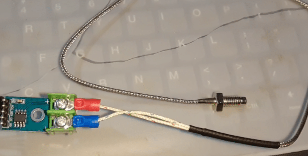
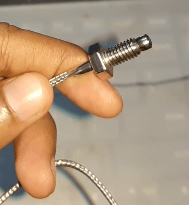
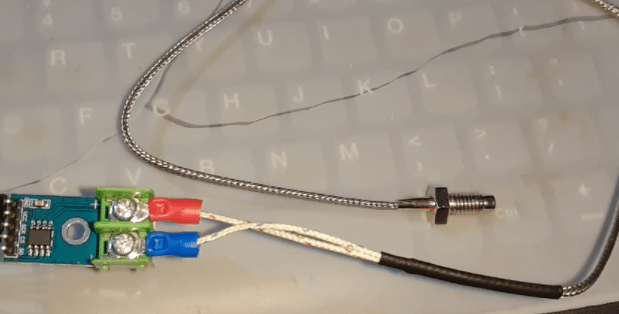
- Thermocouple, which uses the Seebeck effect, generates an EMF by heating one end of two different metals joined together. This EMF helps detect micro-changes and converts them into temperature readings. Here, you will be using the K-type thermocouple to monitor very high temperatures of heated metals and furnaces whose temperature is around 800℃ to 1200℃ and above. The K-type thermocouple sensor consists of two long metal wires made of chromel (positive end) and alumel (negative end)
For measuring the hot part of a furnace or a metal, attach an end of the K-type thermocouple wire junction to it. And because the sensor probe side has two long different metal wires, other electronics parts of the monitoring system can be kept at a safe distance away from such a high temperature. These metal wires are well insulated, which allows them to withstand 1200℃ and above temperatures, and dissipate heat to the environment (see below pic).
The other end of the thermocouple wire is attached to a semiconductor chip that amplifies any small deviation detected in EMF caused due to a temperature change, which is then converted into digital reading and shared over SPI or any other interface. This reading is then processed by a microcontroller or microcomputer and displayed. Here, the MAX6675 amplifies and reads the data from the thermocouple wire, while the MAX6675 gives the temperature reading over SPI. A Raspberry Pi processes the readings and monitors them remotely over WiFi.
Bill Of Materials
| Components | Quantity | Description | Cost Approx INR |
| Raspberry Pi 4 | 1 | SBC | 5000 |
| MAX6675 | 1 | Thermocouple SPI | 200 |
| Thermocouple wire | 1 | Thermocouple Wire | 150 |
| Wires | 1 | Wire | 10 |
| Total | 5360 |
Prerequisites
First, make sure that your Raspberry Pi has the latest Raspbian OS and Python IDLE. Then, install the Python modules and libraries that will help the sensor read values over the SPI interface. There are various libraries and modules available. For this project, I have used the Adafruit MAX6675. Therefore, I have installed its library by running the following command in the Linux terminal:
sudo apt-get update
sudo apt-get install build-essential python-dev python-pip python-smbus git
cd ~
git clone https://github.com/adafruit/Adafruit_Python_MAX31855.git
cd Adafruit_Python_MAX31855
sudo python setup.py install
Coding
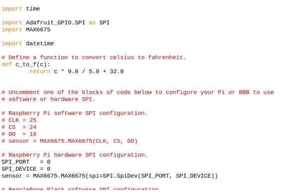
First, import the date and time library, and then the MAX667 library into the code. Then, define the SPI port that you will use. Since this project requires the use of hardware SPI, add the relevant coding part for the same.
Next, save the sensor data with its date and time stamp to enable monitoring of the furnace and other high industrial temperatures. For that, create a while loop, which will keep updating the temperature from the sensor. Now, save it in the furnacedata.txt file as a database.

Connection
Connect the sensor pins to SPIO and GPIO pins of Raspberry Pi.
| Raspberry Pi | MAX6675 |
| MISO (Board Pin 21) | SO |
| SCLK (Board Pin 23) | CLK |
| CE0 (Board Pin 24) | CE |
| 5V | VCC |
| GND | GND |
Testing
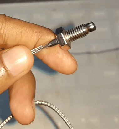
Try measuring temperatures higher than 500°C and later move to more than 1200°C. To do so, first put the device in a safe place away from high temperature (so that minimal electronics get affected by heat) and then place the thermocouple metal junction probe near the source of high temperature. Now, power the Raspberry Pi and run the code. You can see the temperature readings in the Python shell , which gets saved as furnacedb.txt in the database.



Sir,
Thank you for the useful project. The bill of material cost is mentioned as ₹750 and Raspberry Pi 4 cost is mentioned as ₹300. Unbelievable.
Sir, Thank you for the useful circuit and code. Is it possible to implement using Raspberry Pi Pico instead of Raspberry Pi IV?