


 Fuse blowing is a common problem, but is so tedious to go and check because every time it may not be blown. Here is a simple fuse cum power failure indicator for exactly that purpose.
Power failure indicator circuit
This fuse-cum-power failure indicator comprises an LED (LED1), light-dependent resistor (LDR1), inverter circuit and two timer circuits built around IC NE555. LDR1 and preset VR1 form a voltage divider at the input of the cascaded amplifier comprising two BC548 transistors (T1 and T2). The base of transistor T1 is connected to the junction of LDR1 and the preset through resistor R2. The base of transistor T2 is connected to the collector of T1. The trigger pin of timer IC NE555 (IC2), which is configured as a monostable, is connected to the collector of T2. The output of transistor T1 is inverted by transistor T2. The inverted output of T2 triggers the monostable circuit.
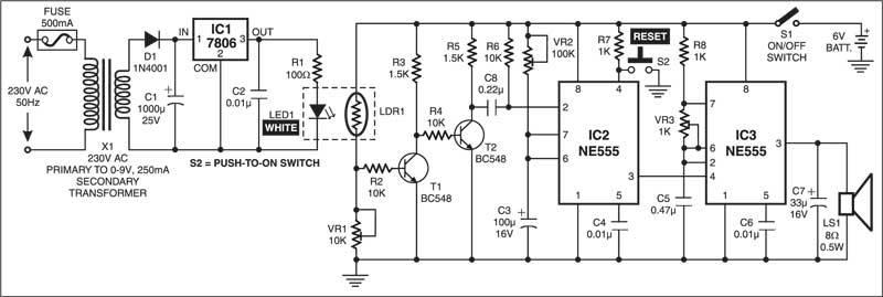
LED1 gets power supply from the AC mains through transformer X1. The secondary output of the transformer is rectified and fed to regulator IC 7806 (IC1). The 6V regulated output drives LED1. As LDR1, enclosed in a cabinet, is kept illuminated by the light from LED1, the output of transistor T2 is normally high.

Circuit operation
The transformer has a fuse on the input side of primary winding. When power supply goes off due to power cut or fuse blown off, no light falls on LDR1 and the output of transistor T2 goes low. This high-to-low transition triggers the monostable (IC2) and its output pin 3 goes high for about 7 seconds. The output of the monostable is connected to reset pin 4 of IC3 (NE555), which is configured in astable mode. The output of the astable circuit is connected to a loudspeaker. IC3, along with the loudspeaker, forms an alarm circuit. Triggering of the monostable activates the alarm circuit, indicating the power failure.
LDR1, cascaded amplifier, monostable and astable circuits get power supply from a 6V battery.

The article was first published in March 2004 and has recently been updated.
