


 In this project, an old Bluetooth headset can be used, along with a cellphone to make a robot controller, without a microcontroller (MCU) or any programming. Communication between the robot car and the smartphone is done via Bluetooth. This is an excellent hacking project and is easy to build.
Circuit and working
The block diagram (Fig. 1) shows how the Bluetooth headset/hands-free can be connected to DTMF receiver, motor driver and power supply. Heart of the circuit is the dual-tone multiple frequency (DTMF) MT8870 decoder. Fig. 2 shows the complete circuit diagram of the receiver system.
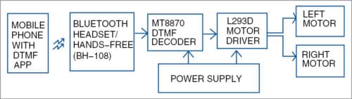
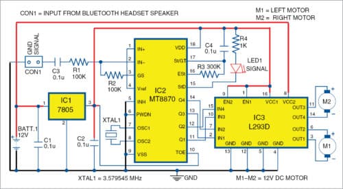
Operating voltage of MT8870 (IC2) is 5V, which is provided by 7805 voltage regulator (IC1). IC2 makes use of a 3.579545MHz crystal oscillator (XTAL1). Input at connector CON1 is an audio signal, which is provided by Bluetooth headset (Nokia BH-108 in this case).
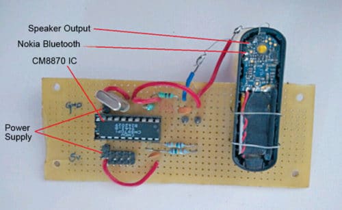
Open Nokia BH-108 Bluetooth headset by removing its top panel, exposing the circuit as shown in Fig. 3. Locate its speaker output terminals (SPK+ and SPK-) on the circuit board. Solder two thin wires onto speaker terminals. Connect the red (signal) wire to input of MT8870 IC through CON1, a filter capacitor C3 (0.1µF) and resistor R1 (100-kilo-ohm).
Make complete connections as shown in the circuit. Output of MT8870 IC goes to the motor control circuit, hence, controlling the two motors (M1 and M2). L293D is used as the motor driver/controller.
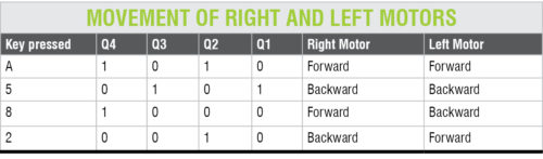
Install an Android app that outputs DTMF tones on the cellphone, whose Bluetooth is paired with Nokia BH-108 Bluetooth headset. Install the app on the cellphone for outputting audio through Bluetooth (such as mono Bluetooth). Now, according to the key pressed in the GUI of the app, the robot will move as per the table. For example, when key A is pressed on the app, output states are 1 0 1 0 for Q4 Q3 Q2 Q1, respectively. As per connections and polarities of motors with output pins of IC3, the robot will move in forward direction. Press 3 to stop the robot.
Construction and testing
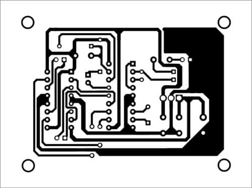
A PCB layout of the robot is shown in Fig. 4 and its components layout in Fig. 5. The robot car is built using two geared motors for rear wheels and a castor wheel on the front. Connect the left and right motors (M1 and M2) to output pins (out1 through out4) of L293D motor driving circuit. Outputs Q1 through Q4 of DTMF IC2 are connected to L293D inputs.
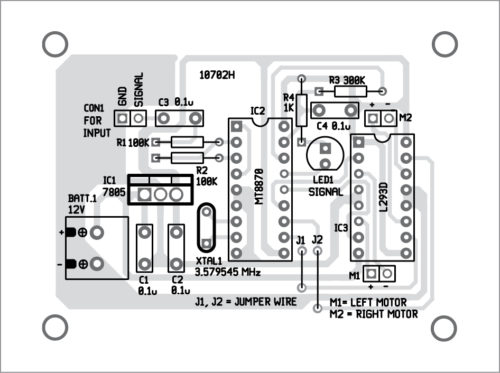
Power supply is provided through a 12V lead-acid battery. For MT8870 and L293D, power supply is provided via 7805 voltage regulator. Bluetooth headset has an inbuilt battery that can be charged using an ordinary phone charger. Charge Bluetooth headset and then pair it with the phone’s Bluetooth.
There are many apps available for DTMF tone generation, such as DTMF by Wolphi LLC. For customisation, or to build your own app of DTMF application, MIT App Inventor can be used. Tonedef app for Android was used during testing at EFY Lab. With this app, you need two cellphones: one (say, A) with DTMF app installed and in user’s hand, and the second cellphone (say, B) with auto answering mode enabled and wirelessly connected to Nokia-BH-108 Bluetooth headset.
The robot is controlled from the first cellphone after connection is established with the second cellphone. Advantage here is that you do not have to keep the second phone on the robot along with Nokia BH-108 Bluetooth headset.
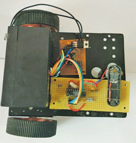
Keep both cellphones with you. Dial the number of phone B from phone A. Once calling is established between the two phones, open DTMF app on phone A. You will see a virtual dialpad. Touch the appropriate number as per the table to control the robot in forward, backward, right or left directions. DTMF signal from phone A is transmitted and received by DTMF decoder MT8870 through BH-108 Bluetooth headset mounted on the robot’s chassis. The author’s prototype is shown in Fig. 6.
Note
You can use any suitable Bluetooth headset for this project.
Download PCB and component layout PDFs: click here
Shashank T.S. is embedded engineer at Adappt Intelligence, Bengaluru. He has keen interest in robotics and artificial intelligence
