 Most battery chargers stop charging the battery when it attains its maximum charging voltage set by the circuit. This 12V battery charger circuit charges the battery at a particular voltage, that is, absorption voltage, and once the maximum charging voltage is attained, the charger changes the output voltage to float voltage for maintaining the battery at that voltage. Absorption and floating voltages are dependent on the type of battery.
For this charger, voltages are set for a sealed lead-acid (SLA) 12V, 7Ah battery, for which absorption voltage is 14.1V to 14.3V and floating voltage is 13.6V to 13.8V. For safe working and to avoid overcharging of battery, absorption voltage is selected as 14.1V and floating voltage is selected as 13.6V. These values are to be set as specified by the battery manufacturer.
12V battery charger circuit
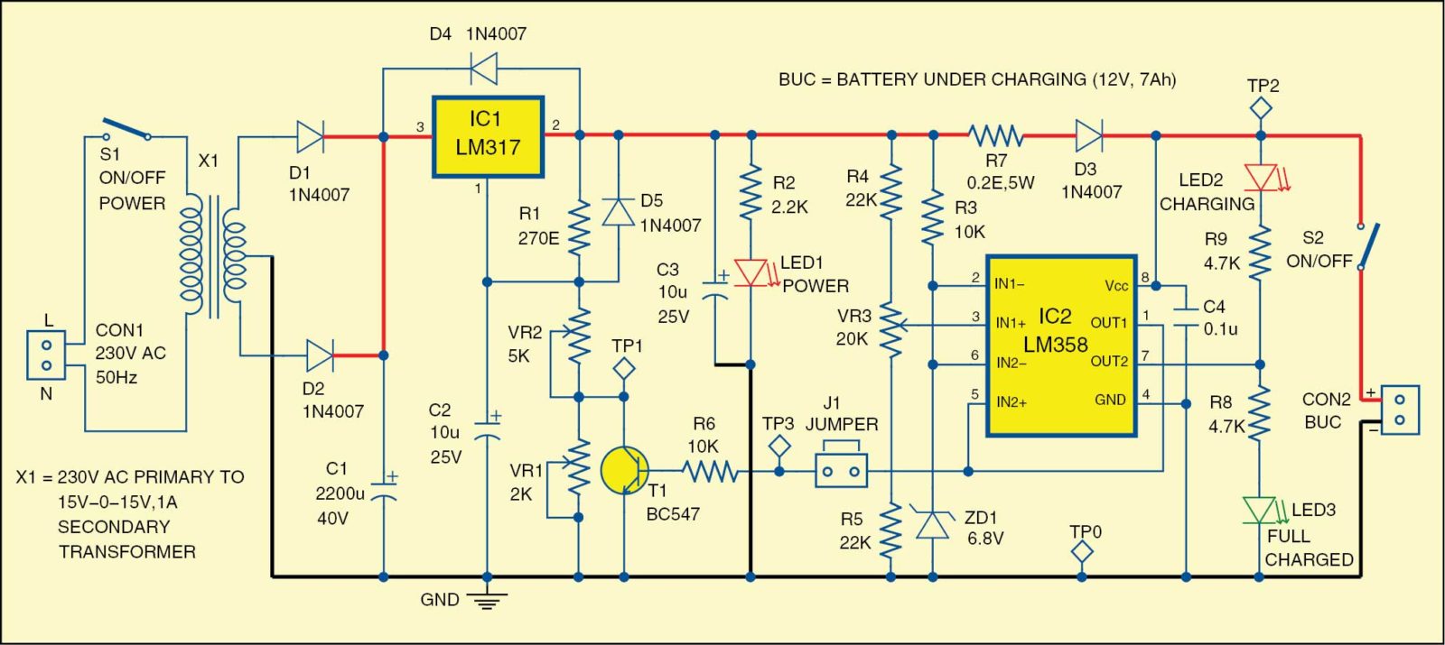
Circuit diagram of the 12V battery absorb and float charger is shown in Fig. 1. It is built around step-down transformer X1, adjustable voltage regulator LM317 (IC1), op-amp comparator LM358 (IC2) and a few other components. The 230V AC primary to 15V-0-15V, 1A secondary transformer used in this circuit steps down mains voltage, which is rectified by diodes D1 and D2 and smoothened by capacitor C1. This voltage is given to the input of LM317 for regulation.
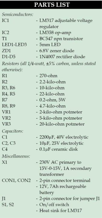
The basic circuit is a regulated power supply using LM317, with a control on output by changing resistance at adjust pin 1. A good heat-sink is required for LM317. LM358 is a dual-operation amplifier that is used here to control overcharging of the battery. Capacitor C4 should be as near as possible to pin 1 of IC2. Jumper J1 is used for calibration (set-up). While setting the charging voltage, remove the jumper and connect it back after calibration.
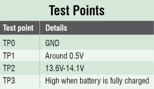
For initial setup, remove jumper J1, switch off S2, switch on S1 and adjust potmeter VR2 to get 13.6V at test point TP2. Adjust potmeter VR3, so that LED2 begins to glow. Adjust potmeter VR1 to read 0.5V (difference of 14.1V and 13.6V) at test point TP1. Adjust VR2 to read 14.1V at test point TP2.
With these settings, TP2 should read 14.1V when there is low voltage at test point TP3, and 13.6V when there is high voltage at test point TP3. Connect jumper J1. The charger is now ready for use. Connect the 12V battery under charging (BUC), with correct polarity, at CON2. Switch on S2; one of the LEDs out of LED2 and LED3 will light up (most likely it would be LED2). If neither of these light up, check the connections; battery could be dead. Switch on S1 for charging. Fully charged status of the battery will be indicated by glowing of LED3.
Do not worry if you forget to switch off the charger. The charger is on floating voltage (13.6V) now and it can be kept in this charging mode forever.
Construction and testing
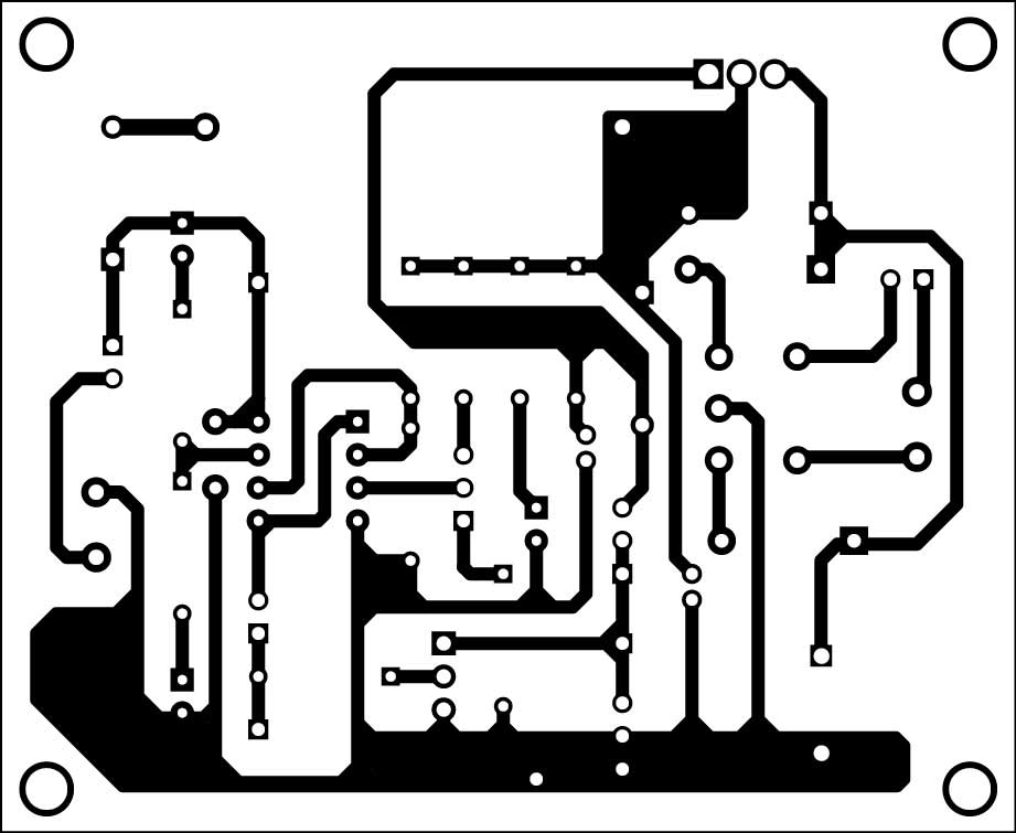
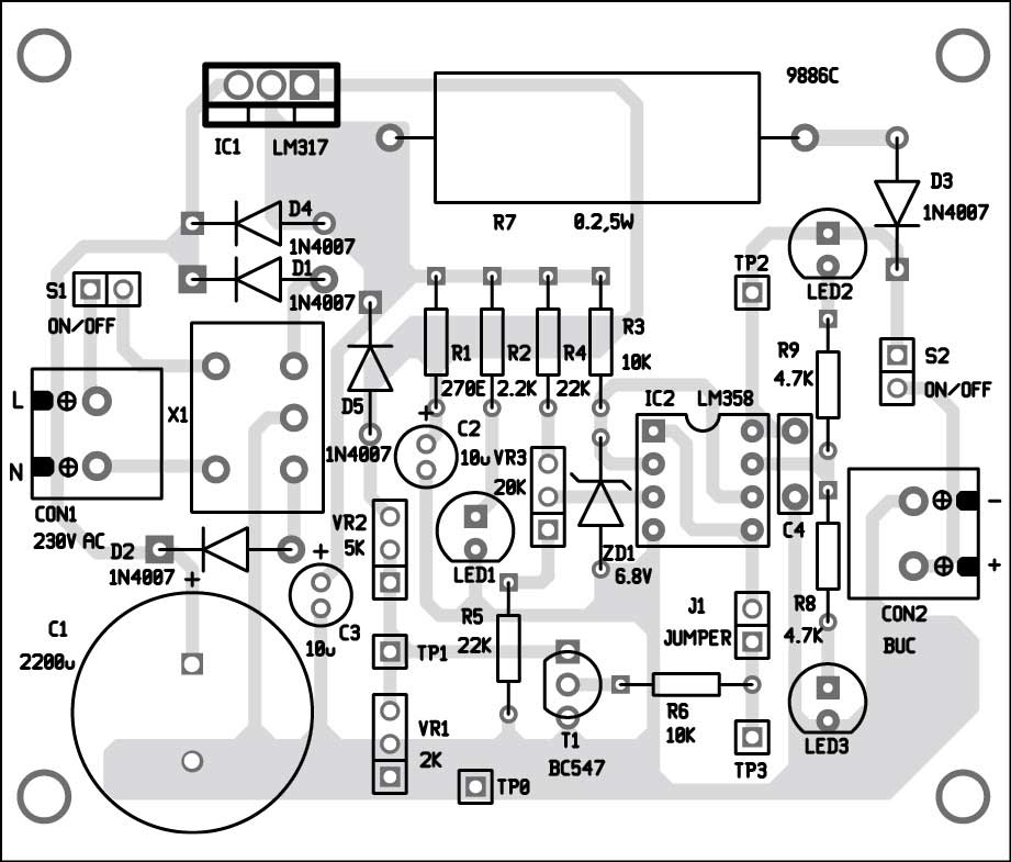
A single-side PCB for the 12V battery absorb and float charger circuit is shown in Fig. 2 and its component layout in Fig. 3. Assemble the circuit on the PCB, except transformer X1 and the battery under charge (BUC).
Download the PCB and component layout PDFs: click here
Enclose the PCB in a small box. Fix the battery terminal on the front of the box for connecting the BUC. Connect switches S1 and S2, potmeters VR1 through VR3, etc on the body of the box.
EFY notes
- Switch off S2 or disconnect battery terminals to avoid unnecessary discharge of battery when not charging, that is, when S1 is switched off.
- Connect the battery with correct polarity.
- Casing of IC1 should not be connected to ground, so use insulation.
Fayaz Hassan is manager at Visakhapatnam Steel Plant, Visakhapatnam, and is interested in microcontoller projects, mechatronics and robotics.




nice and simple
good design with brilliant creativeness
Sir, Thanks for sharing this circuit design. Can it charge my Alto K10’s battery also, which need more current? I have a 12-0-12 5A transformer. Could you help me use it build the charger which can charge my car battery as well as my my bike battery which is 12V/9AH. Many thanks in advance.
Regards,
Jay
A 12V battery requires about 14VDC for charging. About 2VDC will be dropped across the voltage regulator IC. So, 12-0-12 transformer may not sufficient for charging 12V Lead acid battery.
Please refer the project 12V BATTERY CHARGER CUM VARIABLE POWER SUPPLY published in November 2016 EFY edition for higher AH battery charging.
What if the transformer is used with Full Bridge Rectifier? I think, 12-0-12 2Amp Trafo is good. The Full Bridge should use the 2 end terminals and keep the center tap unused. Please confirm if this is true.
This circuit already uses rectifier. You always need to rectify an ac current to turn it into a nice dc current. Bridge rectifier gives the same output as this rectifier. 2 of the 4 diodes are not used in bridge rectifier, I mean, they are there to prevent voltage from running the wrong way. By the way, 12V trafo ac gives about 16.8V dc (12*1.4) that goes in to lm317. Lm317 takes 3V to itself (check datasheet) so the whole circuit uses around 13.8-14V. Since there is D3 in the path to battery, under 1 amp load it drops 1V (check datasheet) so the voltage that goes in the battery is 12.8-13V, and that is not enough to fill any kind of 12V battery.
But if you have 15-0-15, the voltage that goes to battery will be 15.8-16V which is good.
That’s why I asked what if I use end terminals of 12-0-12 trafo which would be around 24*1.4 volts. I won’t use the center tap. Instead I will draw current from the 2 end terminals. That should work, right?
Dear Fayaz Hassan,
Is it possible to use a 18-0-18, 20A transformer that I already have, instead of the 15-0-15 1A described as X1?
I would like to charge a 12V 14ah lead acid battery for a motorcycle but i would like to use it as well for 12V car battery.
Thanks and Regards
Sal
when charging current is more than 1A, the IC1 will start heated up. since your transformer is able to supply more than 1A (where 20A is felt as infinite current in this case), I think, the IC1 will be damaged within no time, if a highly discharged battery is connected for charging.
you can try by connecting about 3.3 ohm, 10W resistance instead of series resistance R7 and reduce to a safe value ( it is trial and error method only ).
Is it possible to use this circuit for 6V battery (instead 12V)?
I was thinking about leaving the in power the same, and only adjusting the circuit with the potmeters with the help of test points, as described in the article. Is this enough or do I also need to change some other components?
By the way, love the led solutions to show each charge state! Very professional!!! Instead of guessing what’s happening, the leds are here to show us. Love it! 🙂
@Sal
Actually, you can’t move 20A through LM 317 because it has a cap of 1.5A. So, in my opinion, LM317 will pull 1.5A in which case you don’t have to change the circuit just add a 1-5C/W heatsink on LM317 or it will shut down. The right c/w for heatsink should be calculated.
To keep heatsink size lower, you can add a small circuit to reduce amp size that will go through ic1 to 1 amp.
Basically, amp is what the load will draw, so even with 30amp transformator, you can only use 1.5A max.
Maybe I’m mistaken, but the 1N4007’s used for rectification only allow 1A to pass through them, so wouldn’t this prevent the use of anything more than a 1A current draw to the LM317? If I’m mistaken, please, show me my error.
Thanks.
Hello,
I’m planning on using 15V-0-15V 1,67A 50VA transformer in this project for charging a 7Ah 12V SLA battery.
Should I increase the value of R7?
Best regards.
Dear sir,
Alls of 3 leds are always light up in my circuit…Pls tell me How to setting them ?
Thanks for advance.
That is the case when you attach a full battery, or the charger finished charging.
If that’s not the case, than you wired something wrong.
Led1 – will always light up because it is connected between the main + line and – line so it always is under power.
Led2 – will light up when you put in a battery to charge. No matter if the battery is fully charged or not, the led will light up and stay on because the battery completes the circuit and now the led is connected between the main + and the OUT2 which acts as a -.
When charging is over, power flows from the OUT2 and goes to LED3 (because it can’t go through LED2 – it’s still a diode and diode rules still apply), but power also flows (actually, it never stopped flowing) to LED2 from main supply (red line) and that’s why LED2 will always glow and LED3 only glows when charging is finished.
Led3 is the ONLY led that will not glow all the time!
For whoever is watching this circuit:
A little improvement can be done to it to make LED2 off when LED3 is on. What you need to do is add another comparator. Instead of using LM358, you can use any other chip that has 4 comparators in it. Basically, it doesn’t matter how many comparator you have in a chip, because you only need to use as much as you need. With this circuit a 4x or 3x chip would be better because you have room for upgrades. Any 4x comparator chip will work.
So, here is how to connect it, but before you do, remove R8 and LED3 from the above circuit:
IN+ on a new chip (or IN3+ if you use a different chip instead of LM358) should be connected to IN2- on this circuit.
IN- (or IN3-) should be connected to IN2+.
The OUT (or OUT3) should be connected to R8. R8 connected to LED3 and LED3 to ground.
That’s all. Now this will work as it should without any confusion.
@Fayaz
I know it’s an old post, but your circuit is still the best one out there that is easy and cheap to make and still works as it should! Great job!
I have LM324. Could you please show me in drawing what will be the new connections if i use it. Thanks.
Can we get an update of dis circuit as u explained? U can send a link so dat everyone can benefit also
Tnx
There is something that I don’t understand in this circuit. If VR3 is just is adjusted when TP2 is 13.6V then how can TP2 get more than 13.4v when it is in charging mode. I think when TP2 get more than 13.6v TP2 will get high voltage and T1 will be open and TP2 never get more than 13.6v. May be I am saying a silly thing, can someone clarify me.
Thanks
can it be used with 24v battery
Nice circuit and good explanation.
But sir,
Can I attach a diode at the battery positive line to Avoide the battery been discharged Wen switch s1 is off?
Dear Sir, We need battery back up system for temperature indicator with some modifications in above circuit. Can you give your e-mail id so that we can give specifications for our requirement.
dear sir
i want to charge my bike battery 12v 17ah what changes are need to be done with this circuit and where can i get the pcb.
i need a charger circuit for 12v and 12 ah battery. i am just a hobbyist. please provide me with an easy solution thank you very much.
How big is the pbc layout?
Sir i want to make my own outdoor speake (trolly type)
With Tda7388. So i need 15v 5amp supply with 12v 7amp sealed battery. Pls suggest how can i arrange this 12v battery charger with 5amp supply pluse online standby battery backup.
Thx.
[email protected]
9216791118, 7888829660
Hello Sir,
I would like to charge a 12V 1.3Ah battery so, in order to limit the charge current to 0.394A, I should change the R7 to 3.2 Ohms right??
If I’m wrong then what is the solution for a 12V 1.3Ah battery?
Dear sir,
Can we use this circuit in electric lunch box …
Can anyone please explain the use of jumper in this circuit?
Hi can you post circuit for 6v 4.2 ah battery charger
The rectifier circuit not work.
I want to create a charger for 12v 7ah battery which will charge battery using solar energy.
Normal 230V AC will be used as backup battery charging voltage incase solar energy is not available.
Can i use same circuit ? Any modifications to be done ??
Sir can u send me a design of this circuit to my mail plz sir it is very urgent and nesesary to me sir
Hi Arun, aLl the details are in the article itself.
Is this circuit only applicable for automobiles and 2 wheelers ? If yes then what changes should be made to make it applicable only for mobile and other electronic handset charging?
Please give me a clarification on this.
Hi…
is there any possibility that instead of tans we use 12.5 v power supply?
thanks
Can I use the same circuit to charge 2 x 12 V Lead Acid Batteries [7 AH] connected in series? – Require 24 V to drive my garage door motor.
hi where could i get the transformer x1 for pcb mounting?
PCB mount transformers are easily available from various online stores such as mouser.com, aliexpress.com, etc. But please note that in this project, we do not use PCB mount transformer.
can we use the battery for powering other applications with sw2 in on state and also the sw1 in on state??
like battery under continuous charging and also being used for powering other applications?
The author Fayaz Hassan replies : YES. The battery can be connected to the load while charging. But,
REMEMBER that the discharge rate (current to the load) should be less than the Charging Rate.
So, the discharge current (to load) should be less than 1 amp. The charger may be kept continuous ON state, which will change its state to either Float or Absorb state automatically.
How can this circuit be used for charging higher amperage 12 Volts batteries like 10 Ampere, 20 Ampere and lower Amperage batteries like 5 Ampere ?
The author Fayaz Hassan replies : The charger can charge any 12V Lead acid battery having charge rate
more than 1A. (please check the charging rate printed on the battery). The problem with the higher AH batteries is, it takes very long time to fully charged. For e.g, w.r.t. 7 Ah battery, the 10 Ah battery requires 1.5 times charging time, 20 Ah requires 3 times charging time, and so on. The total time for fully charging depends on the voltage of the battery before charging and age of the battery.
Hello Sir,
I have built this Battery Charger, it is working fine…
Now, I need to charge 6V battery, Let me know the modification and voltage settings details
Thanks
Vinod C
Good day sir,
Pls how can i upgrade this charger to charge 24v battery of 200to 500amp. And also to incorporate relay and polarity protection
Good day reputable engineer,
How do I modify the charger to charge 24v battery 200-500amp.. and also to incorporate a relay for cutting off.plshelp me out
Please share with me the purpose of diode D4 and resistor R7. Normally when you see a low resistance resistor in series with a current source it is to develop a voltage drop that can be sensed for foldback or crowbar protection circuitry. I don’t think I’m seeing that here. And I am really not understanding the reason for diode D4.
Sincere thanks,
Tom
Good day reputable engineer,
How do I modify the charger to charge 24v battery
Can the same use for charging Automotive lead acid battery 12v 5AH?
I took lot of effort to make PCB and etching . finally, this is not working, the red LED is not gloving it gets only 1.4v in the LED terminal. Green light is always switched on.
You have not mentioned whether you are testing the circuit with or without BUC (battery under charge). Please connect the BUC and try again.
I made this with LM339 (with 4 opms) and works perfectly alright, thanks for the wonderful circuit. I wanted to connect my 12v wifi router as well, so that router works when the power goes off like a ups. When I connect the router in parallel to battery, the voltage drops 0.3 to .5 v and it varies. I am not sure whether the battery charges correctly or not. How can i calibrate it with this setting?
I made the circuit in a PCB. when After calibrating and reconnect the jumper back, the charger output is showing only 13.6v. When I connect to battery the charging indicator glows but the voltage reaches only till 13.6 and not going up, and the green led is not glowing even after many hours. Is it expected to be charged till 14.1v right ? . Not sure what’s wrong with. I rechecked, and all the connection looks correct. I followed the same step mentioned in the article. no luck
Isolate R8 and R9 junction and provide two diodes from pin 7 of ic one forward biase to R8 and one reverse biase to R9
Can I use LM 338 instead of LM317 for charging higher capacity battery and change the value and wattage of R7to suite the charging requirement and also the transformer rating and the rect rating
Reg the tp2 voltage check zd1if it is of lower value tp2 voltage will go down.check R1and vr1and vr2 values check bc547 for collector to emitter short.check the dc voltage across the main filter if every thing ok change Lm317 blindly with a different make. Good luck
for 48 Volt /10 Amp bettery i can use this Circuit by Just replacing Transformer? Also Here which circuit used for Current limitation?
I have a 0-30v output transformer. can I use the same charger circuit to charge 12 v batteries?
It should be center tapped transformer
It is always safe to limit the input voltage of Lm317 to a max of 35 band current to a max of 1 amp even though it can supply up to 1.5 amp above 1 amp and above 35v the ic will get over heatedand it can go defective very soon.in this case you may get around 42v.
Following the datasheet is safe for most of the design
So many electronic parts, no cut off and Very low amperes
I have DC power source of 18v 6~7 A. I want to charge 2 12v7a batteries connected in parallel. what is the current output of this circuit. how can i get 1.4 a at battery charging terminal.
If i use 2-3 amps transformer what changes i need to make in circuit? Thanks
No changes is required even if transformer is rated at 2-3 amps.
it is an unreliable circuit … leave it alone it does not maintain stability, and it is very difficult to obtain the variation of the two voltage thresholds 14.1 and 13.6 volts … the LEDs always light up and in the best hypothesis there is a risk of always having about 13.6v output in any condition !!!