


 Are you in the habit of falling asleep while listening to music? If yes, you’ll love this automatic off timer circuit. It starts functioning when you switch off your bedroom light and will turn your CD player ‘off’ after a predetermined time. In the presence of ambient light, or when you switch on light of the room in the morning, the CD player will again start playing. Unlike the usual timers, you don’t have to set this timer before sleeping.
Automatic off timer circuit
The circuit derives its power directly from the bridge rectifiers. When ‘on’/‘off’ switch S1 is closed, LED1 glows to indicate that the circuit is powered ‘on.’ In the presence of light, the resistance of the light-dependent resistor (LDR1) is low, so transistor T1 conducts to drive transistor T2 into cut-off state and the timer circuit remains inactive.
The collector of transistor T2 is connected to reset pin 12 of IC CD4060 (IC1) via signal diode D5. IC CD4060 is a 14-stage ripple counter with a built-in oscillator. The time period of oscillations (t) is determined by capacitor C3 and resistor R8 connected to pins 9 and 10 of IC1, respectively, as follows:

T=2.3RC
where ‘R’ is the value of resistor R8 and ‘C’ is the value of capacitor C3. When transistor T2 is cut-off, its collector voltage is high. So pin 12 of IC1 is high and IC1 is in reset condition. When light is switched off, the resistance of LDR1 increases, driving transistor T1 into cut-off state.

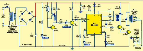
The collector voltage of transistor T1 goes high to light up LED2 (indicating that the timer circuit is enabled) and transistor T2 starts conducting. As the collector voltage of transistor T2 goes low to around 0.2V, ground potential becomes available at reset pin 12 of IC1. The low state at pin 12 enables the oscillator and it starts counting. LED3 at pin 7 of IC1 starts blinking. Its blinking frequency depends on the R-C components connected between its pins 9 and 10. The status of LED2 and LED3 in the circuit with light falling and not falling on LDR1 is given below:

Circuit operation
During counting, in case the power fails momentarily, capacitor C2 (1000µF) will provide the necessary power backup for IC1. That is, during the period, pin 3 of IC1 is low. When output pin 3 of IC1 goes high, the relay is energised through transistors T3 and T4 and, at the same time, counting is disabled by the feedback from pins 3 through 11 (clock input) of IC1 via signal diode D7. That is, due to the feedback, output pin 3 remains high unless another high-to-low pulse is received at its reset pin 12.
After the relay is energised, there will be no AC power in the socket. The glowing of LED5 indicates that your CD player has been switched off.
The desired ‘off’ time period for the timer circuit can be set by choosing proper values of resistor R8 and capacitor C3. If R8 is 680 kilo-ohms and C3 is 0.22 µF, the ‘off’ time period is around 45 minutes. The glowing of LED4 gives the warning that your CD player is going to be switched off shortly. In case you want to extend the timer setting for another round, just press reset switch S2 momentarily. LED4 stops glowing and counting starts again from the initial stage.
The article was first published in December 2005 and has recently been updated.

