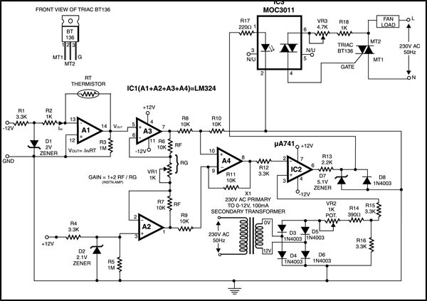
 Here is a circuit through which the speed of a fan can be linearly controlled automatically, depending on the room temperature. This temperature controlled fan circuit is highly efficient as it uses thyristors for power control. Alternatively, the same circuit can be used for automatic temperature controlled AC power control.

In this circuit, the temperature sensor used is an NTC thermistor, i.e. one having a negative temperature coefficient. The value of thermistor resistance at 25°C is about 1 kilo-ohm.
Temperature controlled fan circuit operation
Op-amp A1 essentially works as I to V (current-to-voltage) converter and converts temperature variations into voltage variations. To amplify the change in voltage due to change in temperature, instrumentation amplifier formed by op-amps A2, A3 and A4 is used. Resistor R2 and zener diode D1 combination is used for generating reference voltage as we want to amplify only change in voltage due to the change in temperature.
Op-amp μA741 (IC2) works as a comparator. One input to the comparator is the output from the instrumentation amplifier while the other input is the stepped down, rectified and suitably attenuated sample of AC voltage. This is a negative going pulsating DC voltage. It will be observed that with increase in temperature, pin 2 of IC2 goes more and more negative and hence the width of the positive going output pulses (at pin 6) increases linearly with the temperature. Thus IC2 functions as a pulse width modulator in this circuit. The output from the comparator is coupled to an optocoupler, which in turn controls the AC power delivered to fan (load).
The circuit has a high sensitivity and the output RMS voltage (across load) can be varied from 120V to 230V (for a temp. range of 22°C to 36°C), and hence wide variations in speed are available. Also note that speed varies linearly and not in steps. Besides, since an optocoupler is used, the control circuit is fully isolated from power circuit, thus providing added safety. Note that for any given temperature the speed of fan (i.e. voltage across load) can be adjusted to a desired value by adjusting potmeters VR1 and VR2 appropriately.
Potmeter VR1 should he initially kept in its mid position to realise a gain of approximately 40 from the instrumentation amplifier. It may be subsequently trimmed slightly to obtain linear variation of the fan speed.
For more circuit articles: click here


You guys are great
Thank you for your feedback.
Cool circuit but it needs an RC snubber across the triac since it is driving an inductive load.
I am about starting my project
And i maylikely build temperature controlled fan if is been approved by my co ordinator but right now she is asking me some questions in relation to temperature controlled fan
Twhat are the c ou mponents used in buding temperature controlled fan
Have just made this PCB and tested it with a lamp. The device seems to work but the lamp lights when the NTC is heated and goes off when it is cooled – seems to be some sort of phase reversal.
Also the zener diodes (2v and 2v1) do not reach their zener voltage but do if R1 and R4 are reduced to 1K.
Can you advise please.
Many thanks
What I don’t understand is why is the positive end of the foam diodes connected to GND?
Nice stuff
Thank you for your feedback.