


Battery-life measurement for a portable system is a time-consuming task and many methods used for it do not give reliable results. Presented here is a circuit using which you can measure the battery-life very easily. Here, an analogue clock tracks the discharge time of the battery used in battery-powered portable devices.
Circuit and working
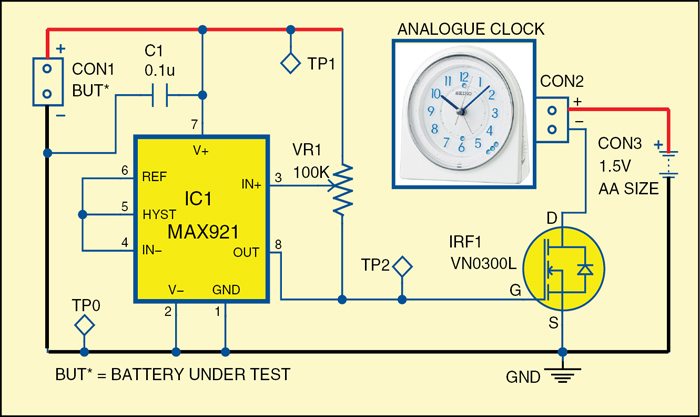
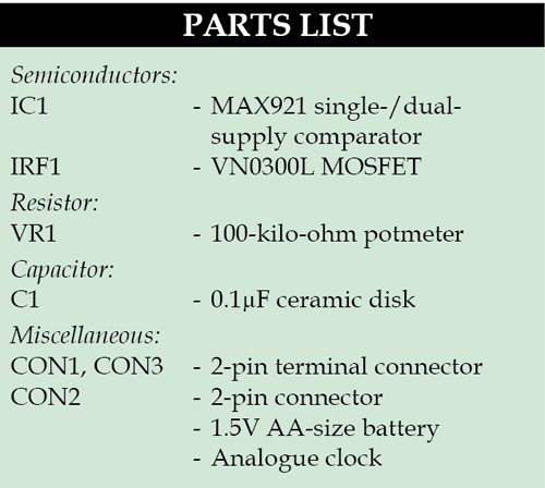
The circuit for battery-discharge measurement is shown in Fig. 1. It is built using low-power single-/dual-supply comparator MAX921 (IC1), MOSFET VN0300L (IRF1), an analogue clock and a few other components.
IC1 monitors the life of the BUT (battery under test) and controls the power supply for the analogue clock. When the BUT voltage falls below the threshold value set by VR1, IC1’s output becomes low, which turns off MOSFET IRF1. This means, power supply for the analogue clock is cut off and so the clock stops running. The reading on the clock at this point gives the discharge time of the BUT, provided you had set the clock to 12:00 before testing started. The circuit can test 2.5V to 11V batteries.


Download PCB and component layout PDFs: click here
Construction and testing
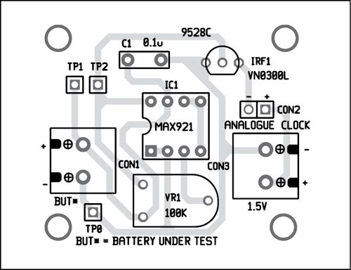
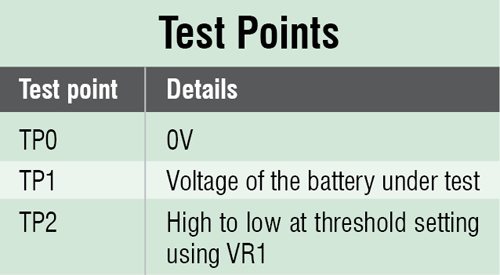 A single-side PCB for the circuit is shown in Fig. 2 and its component layout in Fig. 3. After assembling the circuit on PCB, enclose it in a suitable plastic box. Connect positive terminal of the analogue clock to positive terminal of a 1.5V AA-size battery and negative terminal to the drain of MOSFET IRF1. Before using the circuit, verify that voltages at the test points are as per table.
 For setting the threshold voltage, you need a variable DC power supply at CON1. For example, to measure the discharge time of a 6V battery (BUT), first decide its minimum threshold voltage, say 4.5V. Connect variable supply to CON1 and set it to 4.5V. Vary VR1 till the clock stops running. Now, remove the variable power supply, set the clock to 12:00 and connect the 6V battery at CON1. Connect the load across the battery. As the battery power is being consumed by the load, voltage level begins to drop. When BUT voltage drops below 4.5V, the clock stops running. The time shown on the analogue clock at this point is the discharge time.

The author is an electronics hobbyist.


where can I buy the kit to test batteries
This is exactly what i am looking for, but i would like to test 12v deepcycle batteries. Also, i your circuit, how is the value of Vr1 calculated?