 “An IoT device that works without a battery by simultaneously harvesting multiple energy sources.”
A major challenge for design engineers of IoT devices is powering the device. Power consumption can be reduced if the battery life of the device is more. Sufficient battery life minimises maintenance. Frequent charging of devices is not always possible. Also the frequency of charging required plays an important role in the device utilisation (eg: Electronic Wearables). One way to solve this problem is to make the design of the device more power efficient, while another way is to harvest the ambient energy and use it accordingly.
Surrounded by electromagnetic waves and other sources of energy that continuously dissipate away, this DIY shows how ambient energy can be harvested. This process can in turn, help our IoT devices run longer or better even; we can have a completely batteryless IoT device that could work for years without a battery. This concept, even though in its raw phase, has a huge possibility of exploration.
This project harvests all possible energy sources in the environment and combines it as a single output to power the device . Different types of energy from piezo, solar cells and thermo electric generators, can be harvested.
Video Tutorial:
Bill Of Materials
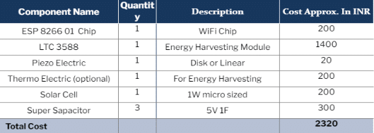
Designing
Since solar energy, heat energy and vibration energy are being harvested here, we need to select the perfect IC. This IC should be capable of harvesting multiple energies simultaneously and combine it to give one output. LTC 3588 Module from Analog Devices’ Linear Technology is used. You can view the data sheet at the following URL for the same.
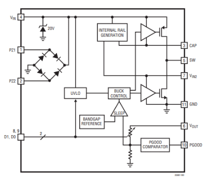
Fig 2. Internal of IC from the LTC 3588 datasheetHere we use the piezoelectric and solar cells to harvest the vibration energy and light energy respectively. The thermoelectric module can be used to harvest the heat energy.
Connection
The LTC 3588 has 4 output modes (1.1V , 2.2V, 3.3V and 3.6V). It also provides the diode solder bridge jumper to select the output voltage mode. This bridge jumper has to be shorted to set the mode, before the design. Here we use the ESP8266 1 module whose working voltage is 3.3V and the minimum current consumption is 70m – 80mA.
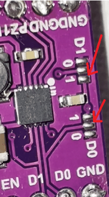
Our LTC 3588 module is able to provide 100mA after harvesting the energy to its full capacity but we need to set the output voltage range to 3.3V. The diode solder bridge jumper sets the output voltage. To set the different output voltage, the solder bridge jumper settings are as follows.
(D1, D0) – VOUT
(0, 0) – 1.8V
(0, 1) – 2.5V
(1, 0) – 3.3V
(1, 1) – 3.6V
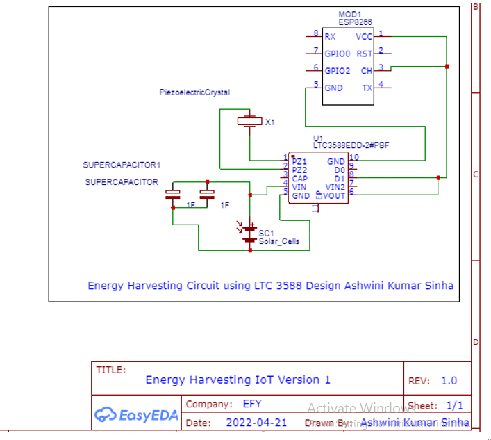
Hence we solder D1 to 1 and D0 to 0, setting the output mode to 3.3 V as seen in figure 4.
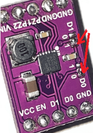
Now we need to connect the super capacitor in series with its +ve terminal to the +ve of solar and vice versa. The solar output pin has to be connected to the LTC 3588 Vin Pin . The PZ1 and PZ2 pins should be connected to the piezoelectric transducer to harvest the vibration energy. For any other energy sources, relevant connections can be made to the other transducer (eg: thermoelectric). The Vout and D1 pins of the LTC3588 Chip are used to power the ESP or another IoT device CHIP like BLE. These chips use a 3.3V range and consume current between 2mA to 80mA. Hence the connections are made as per the circuit diagram shown in figure 5.

Now fix the ESP chip and LTC harvester module to make it small in size and connect the transducer for it to start working.
Testing

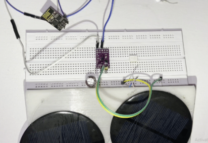
Place the device in a proper lighting ambience and then hit the piezo and other transducers. The energy harvesting device is now powered on and will light up the ESP 01 chip. In this manner the energy harvesting device can be done easily and we can consume less power.
NOTE: This IoT device can run forever without the need of a battery, only if sufficient light is available.


