


 Whether you are a science fiction fan, a space enthusiast or one of the millions who have watched astronauts gamboling about the moon’s surface, you may have wondered how much you would weigh on other planets in the solar system. The weight depends on the gravitational forces acting on the object, which vary from planet to planet. The Newton’s law of universal gravitation says that everything that has mass attracts every other thing that has mass, pulling with a force which is directly proportional to the product of the two masses of the objects and inversely proportional to the square of the distance separating their centres. The mass and radius of different celestial bodies is mentioned in Table I.
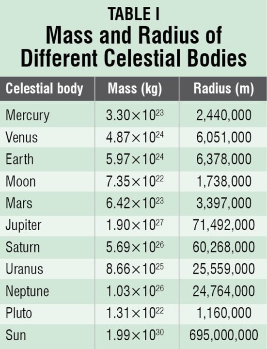
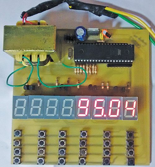
The designed embedded system takes a weight on earth and shows the weights on other celestial bodies of our solar system. The device is designed and constructed using microcontroller AT89S52. It can give better understanding about gravity. The system calculates the mass and acceleration due to gravity (g) for other celestial bodies and displays the corresponding weight (force). Fig. 1 shows the author’s prototype.

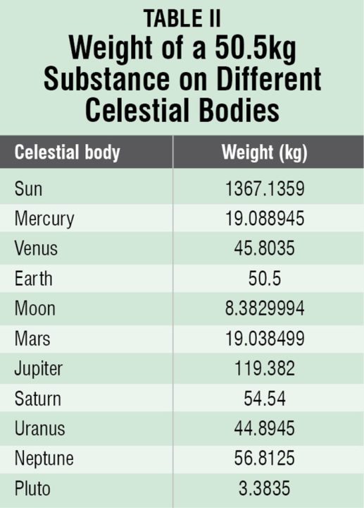
Suppose your weight on earth is 50.5 kg, your weight on other celestial bodies of our solar system would be as given in Table II.
 Circuit and working
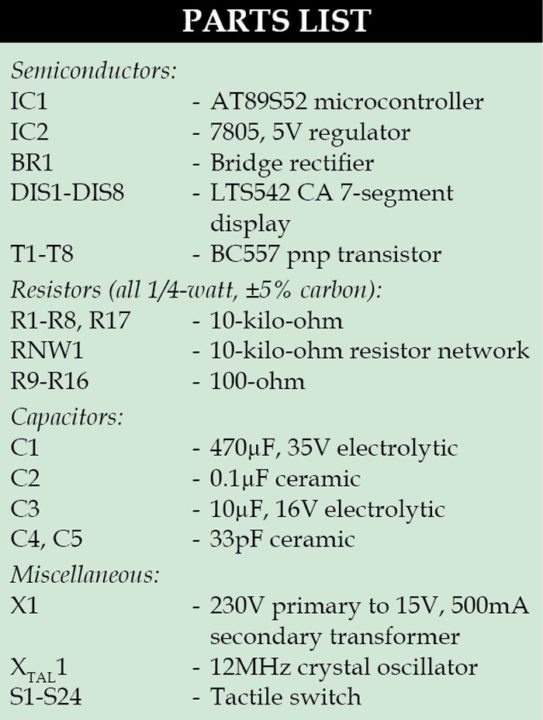 Fig. 2 shows circuit diagram of the celestial weight calculator. The circuit is built around microcontroller AT89S52 (IC1), 7-segment displays LTS542 (DIS1 through DIS8), and a few transistors and switches.

Microcontroller
AT89S52 is a low-power, high-performance CMOS 8-bit microcontroller. It provides 8k bytes of Flash, 256 bytes of RAM, 32 I/O lines, three 16-bit timer/counters, a six-vector two-level interrupt architecture, a full-duplex serial port, on-chip oscillator and clock circuitry. Power-on reset is provided by the combination of resistor R17 and capacitor C3. Switch S6 is used for manual reset. A 12MHz crystal along with two 33pF capacitors provides basic clock frequency to the microcontroller.
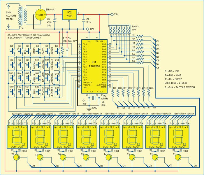
Port 0 and port 2 of IC1 are used for multiplexing the 7-segment displays (DIS1 through DIS8). The port 1 and port 3 are used for scanning the keyboard buttons, except switch S6. Transistors (T1 through T8) and resistors (R1 through R8) are used for digit selection. The 7-segment displays used are LTS542, which are common-anode type. Eight current-limiting resistors (R9 to R16) of 100Ω each are used.
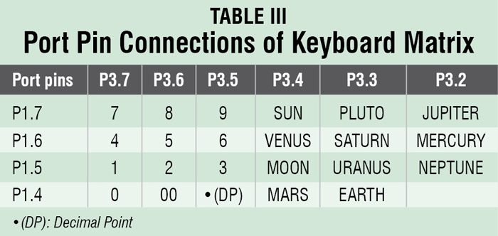
The pin connections between the matrix keyboard and IC1, with key functions, are shown in Table III.
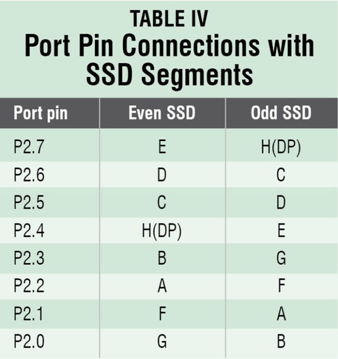
 The multiplexing of eight 7-segment displays is done by using unconventional queer multiplexing technique. The even and odd segments are connected differently in this technique to make the PCB design simpler, as shown in Table IV.
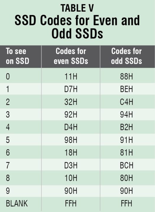
The codes to display different numbers on even and odd 7-segment displays are shown in Table V.
 The working of this device is very simple. Switch on the power supply and the device will display ‘0.’ Enter your weight on earth (either integer or real number). After entering weight press key for any celestial body and see the weight at that celestial body. To enter a new weight on earth, press Reset key.
Software
The source program for the microcontroller is written in C language and compiled using Keil µVision4 compiler. The generated hex code is burnt into the microcontroller using a suitable programmer. On reset/power-on, the microcontroller executes the main function.
Construction and testing
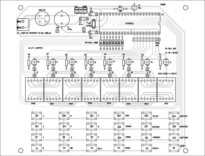
A single-side PCB for the celestial weigh calculator is shown in Fig. 3 and its component layout in Fig. 4. Assemble the circuit on PCB to save time and minimize assembly errors. Carefully assemble the components and double-check for any overlooked error.
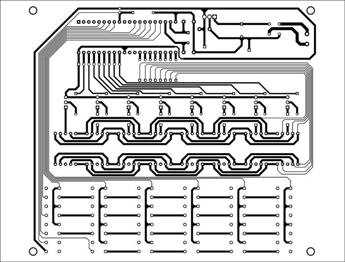
Download PCB Pattern and Component Layout PDF: Click Here
Download Source Code: Click Here
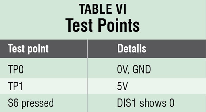
To test the circuit for proper functioning, verify correct 5V supply for the circuit at TP1 with respect to TP0.
The author works in the department of Physics, Hemchandracharya North Gujarat University, Patan, Gujarat