


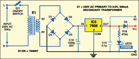
Fig.3 shows the power supply circuit. The 230V AC mains is stepped down by transformer X1 to deliver the secondary output of 9V, 500 mA. The transformer output is rectified by a full-wave bridge rectifier comprising diodes D1 through D4, filtered by capacitor C16 and then regulated by IC 7806 (IC5). Capacitor C15 bypasses the ripples present in the regulated 6V power supply. LED3 acts as a power-on indicator and resistor R16 limits the current through LED3.
An actual-size, single-side PCB for cellphone-based device control with voice acknowledgement is shown in Fig.4(View as PDF) and its component layout in Fig.5(View as PDF).
Download PCB and component layout PDFs: click here

Download Source code: click here
Recording and playback

To record the voice in IC2, follow Table III. Close SPST switch S19 to make pin 27 of IC2 low. Thereafter, press and hold switches S9 through S16 to record corresponding voice messages. LED2 flashes to indicate audio recording.
For playback of any device status, open SPST switch S19 and press the corresponding switch (S9 through S16). The recorded audio can be heard from the speaker connected to pins 14 and 15 of IC2. Fig.2 shows the pin configuration of mobile headset.
Software
The program (Device_Control.BAS) for the microcontroller is written using BASCOM microcontroller programming software. In the program, first, initialise the port (P0-P3) for corresponding controls. Thereafter, declare the variables for the program. After declaration, assign some initial value to variables. Here, microcontroller ports are initialised to make all the devices ‘off’ initially.
After that, the main function checks through ‘Do’ loop which control source has been enabled by using DIP switch pins. If you select switch S17, it searches the input from the mobile only. If you select switch S18, it searches the input from the switches (S1 through S8) only. If you enable both switch S17 and switch S18, it searches the inputs from switches and mobile. Else, the rest-status LED1 glows. Refer to Table II to select the control source.
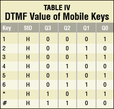
The mobile signal is decoded into the DTMF signal by IC3. The DTMF output for each mobile key (used in this project) pressed is shown in Table IV.
After getting the input from the switches or mobile, the program goes to the device_action subroutine and executes the corresponding action (refer Table I).
The device_action subroutine changes the status of the device and calls the voice_alert subroutine. The voice_alert subroutine checks the device status and device name from the source input and controls the corresponding pins of IC2. First, it selects the voice signal for the device name. After playing that, it selects on/off status of corresponding device as mentioned in Table III.
If you press ‘*’ key followed by the device number on your mobile handset, it will not change the status of that device and inform the current device status. If you press device number followed by ‘*’ key on your mobile handset, it will change the status of that device and inform the changed device status. ‘#’ key controls the voice_control subroutine and acts like a mute key.
