


 Conventionally, wireless-controlled robots use RF circuits,which have the drawbacks of limited working range, limited frequency range and limited control. Use of a mobile phone for robotic control can overcome these limitations. It provides the advantages of robust control, working range as large as the coverage area of the service provider, no interference with other controllers and up to twelve controls.
Although the appearance and capabilities of robots vary vastly, all robots share the features of a mechanical, movable structure under some form of control. The control of robot involves three distinct phases: preception, processing and action. Generally, the preceptors are sensors mounted on the robot, processing is done by the on-board microcontroller or processor, and the task (action) is performed using motors or with some other actuators.
Project overview
In this project, the robot is controlled by a mobile phone that makes a call to the mobile phone attached to the robot. In the course of a call, if any button is pressed, a tone corresponding to the button pressed is heard at the other end of the call. This tone is called ‘dual-tone multiple-frequency’ (DTMF) tone. The robot perceives this DTMF tone with the help of the phone stacked in the robot.

The received tone is processed by the ATmega16 microcontroller with the help of DTMF decoder MT8870. The decoder decodes the DTMF tone into its equivalent binary digit and this binary number is sent to the microcontroller. The microcontroller is pre-programmed to take a decision for any given input and outputs its decision to motor drivers in order to drive the motors for forward or backward motion or a turn.
The mobile that makes a call to the mobile phone stacked in the robot acts as a remote. So this simple robotic project does not require the construction of receiver and transmitter units.
DTMF signaling is used for telephone signaling over the line in the voice-frequency band to the call switching centre. The version of DTMF used for telephone tone dialing is known as ‘Touch-Tone.’
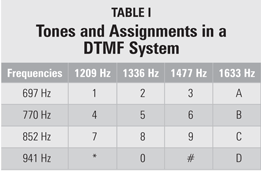
DTMF assigns a specific frequency (consisting of two separate tones) to each key so that it can easily be identified by the electronic circuit. The signal generated by the DTMF encoder is a direct algebraic summation, in real time, of the amplitudes of two sine (cosine) waves of different frequencies, i.e., pressing ‘5’ will send a tone made by adding 1336 Hz and 770 Hz to the other end of the line. The tones and assignments in a DTMF system are shown in Table I.
Circuit description

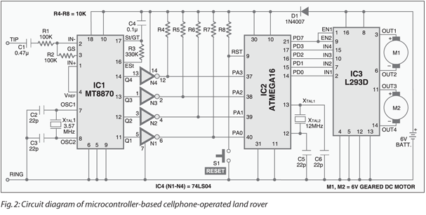
Fig. 1 shows the block diagram of the microcontroller- based mobile phone-operated landrover. The important components of this rover are a DTMF decoder, microcontroller and motor driver.
An MT8870 series DTMF decoder is used here. All types of the MT8870 series use digital counting techniques to detect and decode all the 16 DTMF tone pairs into a 4-bit code output. The built-in dial tone rejection circuit eliminates the need for pre-filtering. When the input signal given at pin 2 (IN-) in single-ended input configuration is recognised to be effective, the correct 4-bit decode signal of the DTMF tone is transferred to Q1 (pin 11) through Q4 (pin 14) outputs.
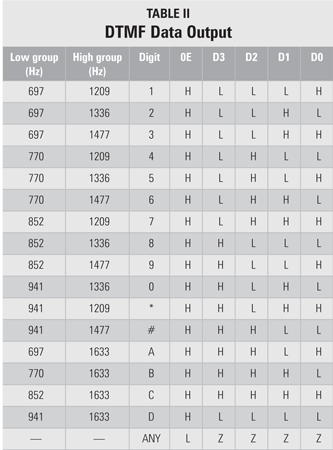
Table II shows the DTMF data output table of MT8870. Q1 through Q4 outputs of the DTMF decoder (IC1) are connected to port pins PA0 through PA3 of ATmega16 microcontroller (IC2) after inversion by N1 through N4, respectively.
The ATmega16 is a low-power, 8-bit, CMOS microcontroller based on the AVR enhanced RISC architecture. It provides the following features: 16 kB of in-system programmable Flash program memory with read-while-write capabilities, 512 bytes of EEPROM, 1kB SRAM, 32 general-purpose input/ output (I/O) lines and 32 general-purpose working registers. All the 32 registers are directly connected to the arithmetic logic unit, allowing two independent registers to be accessed in one single instruction executed in one clock cycle. The resulting architecture is more code-efficient.
Outputs from port pins PD0 through PD3 and PD7 of the microcontroller are fed to inputs IN1 through IN4 and enable pins (EN1 and EN2) of motor driver L293D, respectively, to drive two geared DC motors. Switch S1 is used for manual reset. The microcontroller output is not sufficient to drive the DC motors, so current drivers are required for motor rotation.
The L293D is a quad, high-current, half-H driver designed to provide bidirectional drive currents of up to 600 mA at voltages from 4.5V to 36V. It makes it easier to drive the DC motors. The L293D consists of four drivers. Pins IN1 through IN4 and OUT1 through OUT4 are input and output pins, respectively, of driver 1 through driver 4. Drivers 1 and 2, and drivers 3 and 4 are enabled by enable pin 1 (EN1) and pin 9 (EN2), respectively.When enable input EN1 (pin 1) is high, drivers 1 and 2 are enabled and the outputs corresponding to their inputs are active. Similarly, enable input EN2 (pin 9) enables drivers 3 and 4.
An actual-size, single-side PCB for cellphone-operated land rover is shown in Fig. 4 (View PDF) and its component layout in Fig. 5 (View PDF).
Software description
The software is written in ‘C’ language and compiled using CodeVision AVR ‘C’ compiler. The source program is converted into hex code by the compiler. Burn this hex code into ATmega16 AVR microcontroller.
The source program is well commented and easy to understand. First include the register name defined specifically for ATmega16 and also declare the variable. Set port A as the input and port D as the output. The program will run forever by using ‘while’ loop. Under ‘while’ loop, read port A and test the received input using ‘switch’ statement. The corresponding data will output at port D after testing of the received data.
Working
In order to control the robot, you need to make a call to the cell phone attached to the robot (through head phone) from any phone, which sends DTMF tunes on pressing the numeric buttons. The cell phone in the robot is kept in ‘auto answer’ mode.
(If the mobile does not have the auto answering facility, receive the call by ‘OK’ key on the rover connected mobile and then made it in hands-free mode.) So after a ring, the cellphone accepts the call.
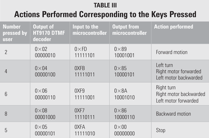
Now you may press any button on your mobile to perform actions as listed in Table III. The DTMF tones thus produced are received by the cellphone in the robot. These tones are fed to the circuit by the headset of the cellphone. The MT8870 decodes the received tone and sends the equivalent binary number to the microcontroller. According to the program in the microcontroller, the robot starts moving.
When you press key ‘2’ (binary equivalent 00000010) on your mobile phone, the microcontroller outputs ‘10001001’ binary equivalent. Port pins PD0, PD3 and PD7 are high. The high output at PD7 of the microcontroller drives the motor driver (L293D). Port pins PD0 and PD3 drive motors M1 and M2 in forward direction (as per Table III). Similarly, motors M1 and M2 move for left turn, right turn, backward motion and stop condition as per Table III.
Construction
When constructing any robot, one major mechanical constraint is the number of motors being used. You can have either a two-wheel drive or a four-wheel drive. Though four-wheel drive is more complex than two-wheel drive, it provides more torque and good control. Two-wheel drive, on the other hand, is very easy to construct.
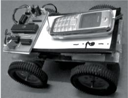
Top view of a four-wheel-driven land rover is shown in Fig. 3. The chasis used in this model is a 10×18cm2 sheet made up of parax. Motors are fixed to the bottom of this sheet and the circuit is affixed firmly on top of the sheet. A cellphone is also mounted on the sheet as shown in the picture. In the four-wheel drive system, the two motors on a side are controlled in parallel. So a single L293D driver IC can drive the rover. For this robot, beads affixed with glue act as support wheels.
Further applications
This land rover can be further improved to serve specific purposes. It requires four controls to roam around. The remaining eight controls can be configured to serve other purposes, with some modifications in the source program of the microcontroller.
ROBOT.C
Source program:
Robit.c
#include
void main(void)
{
unsigned int k, h;
DDRA=0x00;
DDRD=0XFF;
while (1)
{
k =~PINA;
h=k & 0x0F;
switch (h)
{
case 0x02: //if I/P is 0x02
{
PORTD=0x89;//O/P 0x89 ie Forward
break;
}
case 0x08: //if I/P is 0x08
{
PORTD=0x86; //O/P 0x86 ie Backward
break;
}
case 0x04:
{
PORTD=0x85; // Left turn
break;
}
case 0x06:
{
PORTD=0x8A; // Right turn
break;
}
case 0x05:
{
PORTD=0x00; // Stop
break;
}
}
}
}

Good
what is the use for this project?