


 A camera is one of the most powerful and accurate sensors if you know how to process the images taken by it for the information you want. You can process subsequent images and extract a variety of information using image-processing techniques. MATLAB is a very powerful tool and plays an important role in image processing.
Image processing is converting an image into digital form and performing some mathematical operations on it, in order to get an enhanced image or to extract some useful information out of it. Most image-processing techniques involve treating the image as a two-dimensional signal and applying standard signal-processing techniques to it.
Presented here is a MATLAB-based project where images taken by the camera are processed for colours and the position of a red-coloured object is extracted out of the image. Based on the position of the red coloured object in the image, different data are sent via COM port. The serial data are received by the robot and corresponding movement is done. You can change the code for any colour that you find suitable. This project is just an example and you can use this for various industrial applications such as controlling heavy load-lifting machines with some object of a specific colour in your hand.

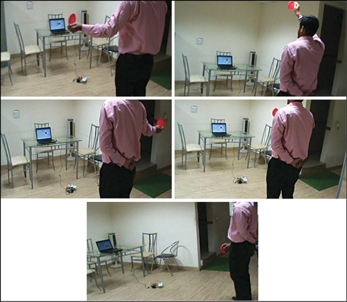
Coloured object can be held in your hand, which instructs the robot to move right, left, forward or backward as per the position of your hand, as shown in Fig. 1.
Circuit and working
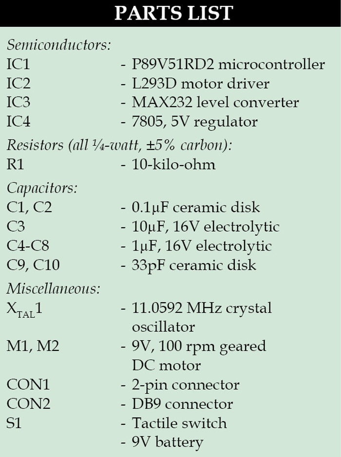
Fig. 2 shows the circuit of the robot, which uses microcontroller P89V51RD2 (IC1) to receive serial data from the computer through driver IC MAX232 (IC3). The received data is analysed by the microcontroller IC1 and the motors are controlled through motor-driver IC L293D (IC2). The power supply for the robot comes from a 9V battery which is regulated to 5V by regulator 7805 (IC4). 9V is also connected to pin 8 for IC2 for the motors.
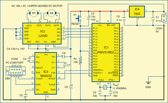
 The USB port of the computer is connected to the robot through USB-to-serial converter. Controlling commands to the robot are sent via serial port and the signal levels are converted into 5V TTL/CMOS type by IC3. These signals are directly fed to microcontroller IC1 for controlling motors M1 and M2 to move the robot in all directions. Port pins P1.0 through P1.3 of IC1 are connected to the inputs of IN4 through IN1 of IC2, respectively, to give driving inputs. EN1 and EN2 are connected to Vcc to keep IC2 always enabled.
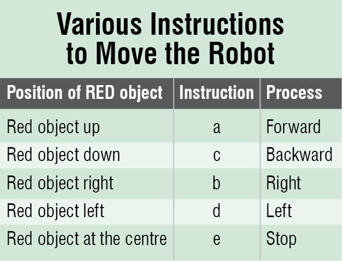
The application running on the computer interprets the position of the coloured object and sends corresponding commands to the robot through the serial port. As shown in the pictures in Fig. 1, if the operator stands in front of the computer’s camera, holds a red-coloured object in his hand and raises his hand up, the MATLAB application running in the computer interprets the position of the coloured object and sends ‘a’ to the serial port. The robot is programmed to move forward if it receives ‘a’ from the serial port. Similarly, for other positions, the letters are listed in the table, which are sent through the serial port to the robot.
Software
 The program for the robot is written in C language using Keil compiler and the hex file is programmed in the microcontroller chip with a suitable programmer. The application running on the computer to interpret the position of coloured object is designed using MATLAB. The application uses colour-detection algorithm to detect the coloured object and then finds out its coordinates to detect the position.
Colour detection algorithm. In colour-detection algorithm, the primary-colour (red, green and blue) objects can be detected easily. The algorithm used for colour detection actually works in separate steps as follows:
1. Take the snapshot (image) from the real video
2. Convert that original snapshot to grey
3. Extract the red coloured components from the original snapshot
4. Now subtract the red coloured components from the grey coloured snapshot
5. Remove the noise from the image by using filter command
6. Convert that filtered image into binary image and you will get an image that is bright at the place of red object
7. Then find the coordinates of the bright portion
MATLAB program. MATLAB provides a GUI development platform where engineers can develop an aesthetic graphic interface for their application. The program first initialises and starts the video by using the functions mentioned below:
vid = videoinput(‘winvideo’,1,’YUY2
_320x240’);
set(vid, ‘FramesPerTrigger’, Inf);
set(vid, ‘ReturnedColorspace’, ‘rgb’)
vid.FrameGrabInterval = 2;
start(vid)
Some important functions used in the program are:
data = getsnapshot(vid). This function immediately returns single-image frame from the video input object
img = rgb2gray(data). Converts the true-colour image RGB to the grey-scale intensity image
data(:,:,1). Extracts all the red coloured components from the real image
Similarly, for green: data(:,:,2) and for blue: data(:,:,3)
diff_im = imsubtract(data(:,:,1), rgb2gray(data)). Used to subtract red components from the grey image
B = medfilt2(diff_im, [3,3]). Median filtering is a non-linear operation often used in image processing to reduce ‘salt and pepper’ noise. A median filter is more effective than convolution when the goal is to simultaneously reduce noise and preserve edges
diff_im = im2bw(diff_im, 0.18). Converts the greyscale image to a binary image. The output image ‘diff_im’ replaces all pixels in the input image with luminance greater than level with the value 1 (white) and replaces all other pixels with the value 0 (black)
stats = regionprops(diff_im, ‘BoundingBox’,’Centroid’). Measures a set of properties for each connected component (object) in the binary image. The image stats is a logical array and can have any dimension
By using ‘regionprops ( )’ function, we find the coordinates of centroid and bounding box as follows:
stats = regionprops(diff_im,
‘BoundingBox’, ‘Centroid’);
for object = 1:length(stats)
bb = stats(object).BoundingBox;
bc = stats(object).Centroid;
The ‘Centroid’ in the code specifies the centre of mass of the region. Note that the first element of centroid is the horizontal coordinate (or x-coordinate) of the centre of mass, and the second element is the vertical coordinate (or y-coordinate). Once we get the coordinates, we define conditions for the object’s position and corresponding data to be sent to the robot as follows:
if (bc(1)>110 && bc(1) 110 && bc(2) < 170)
> 110 && bc(2) < 170)
We also get the idea of the current position of the object on GUI using the code below:
if (bc(1)>110 && bc(1) 110 && bc(2) < 170)
axes(handles.axes5);
imshow(‘red2.jpg’);
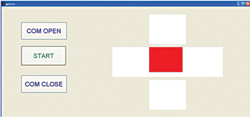
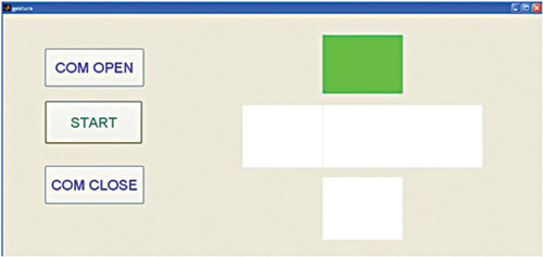
Fig. 4 indicates the position of the object in the defined centre range and Fig. 5 indicates that the object is raised to give a forward signal. The same is done for left, right, forward and backward movement.
Construction and testing
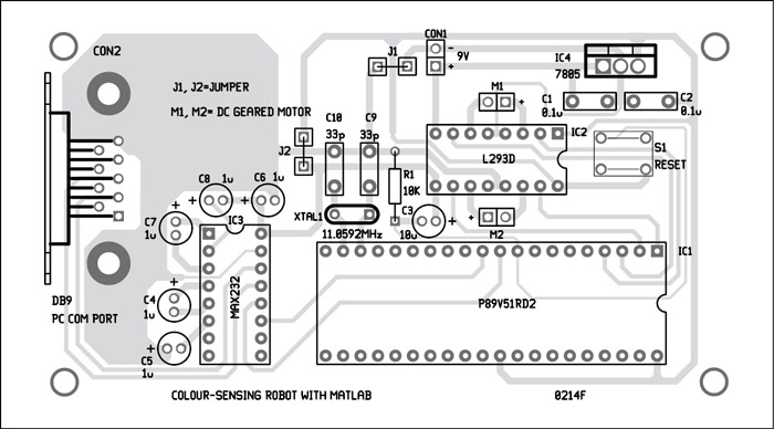
An actual-size, single-side PCB for the robot is shown in Fig. 6 and its component layout in Fig. 7. Assemble the components on the PCB and connect the motors and battery to build the robot. Use suitable bases for the ICs. Before inserting the MCU in the circuit burn the code into it using a suitable programmer. Connect the robot to the computer either through the serial port or USB port (using USB-to-serial converter) and check whether the USB-to-serial converter is detected or not in the device manager and change the COM port with respect to it.
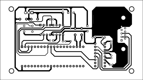
Download the PCB and Component Layout PDFs: click here
Download Source Code: click here
Install MATLAB 7.10 or higher version in your system. Once it is installed, connect it to the robot. Also check which COM port you are using and write the same COM port in the code, otherwise you will get an error.
Run application
Once the setup is ready, follow the below-mentioned steps:
1. Download the required source code folder from this month’s EFY DVD.
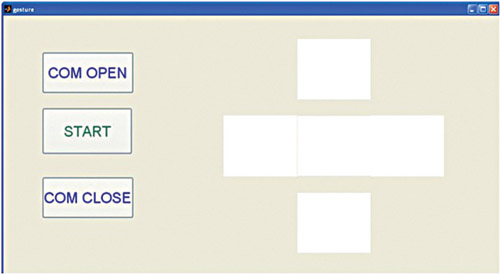
2. Run the program gesture.m and a GUI will appear as shown in Fig. 3.
3. Click on COM OPEN button to open the COM port.
4. click on START and stand in front of the computer’s camera or webcam with the red-coloured object in your hand.
5. move the object up, down, left and right, and MATLAB program will send the data to the microcontroller according to the position of the object and the robot will move according to the values the microcontroller is receiving.
The author is a B.Tech in electronics and communications from SRCEM, Gwalior (MP)

I’m having this error
Error using serial/fopen (line 72)
Open failed: Port: COM5 is not available. No ports are available.
Use INSTRFIND to determine if other instrument objects are connected to the requested device.
Error in gesture>pushbutton3_Callback (line 226)
fopen(handles.ser); % to open the communication port
Error in gui_mainfcn (line 95)
feval(varargin{:});
Error in gesture (line 42)
gui_mainfcn(gui_State, varargin{:});
Error in
matlab.graphics.internal.figfile.FigFile/read>@(hObject,eventdata)gesture(‘pushbutton3_Callback’,hObject,eventdata,guidata(hObject))
Error while evaluating UIControl Callback.
when i click on open com button in GUI screen please rpl with a solution
at my email [email protected]