


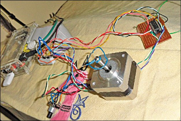
Presented here is a project for controlling stepper motor using rotary encoder. It consists of a Raspberry Pi (Raspi) board, 5-pin rotary encoder, 5V stepper motor and an L293D motor driver. Author’s prototype is shown in Fig. 1.
A rotary encoder, also called a shaft encoder, is an electromechanical device that converts the angular position or motion of a shaft or an axle to analogue or digital code.
There are two main types: absolute and incremental (relative). Output of the absolute encoder indicates the current position of the shaft, making it an angle transducer. Output of the incremental encoder provides information about the motion of the shaft, which is further processed elsewhere into information such as speed, distance and position.

Rotary encoders are used in various applications that require precise but unlimited shaft rotation, including industrial controls, robotics, special-purpose photographic lenses, computer input devices (such as optomechanical mice and trackballs), controlled stress rheometers and rotating radar platforms.
Raspberry Pi in action
Here is the solution based on Raspi using a rotary encoder to drive a stepper motor.

The rotary encoder is an easy, efficient and inexpensive device for creating directional rotation in digital format. A typical rotary encoder has three or more leads, wherein the common lead goes to ground.
By following which lead goes to ground through the common lead, a direction of rotation is established and a counter is incremented at the same time.
Each movement of the rotary encoder is read by the program and fed to the stepper motor for making the same amount of stepped movement. This principle can be employed to control feeding of the heavy motor control such as in a paddle feeder.
The same technique can be employed for aligning a telescope’s focus mechanism, direction of a dish antenna to re-adjust satellite drifting, mast of a crane for placing it on the load and much more.
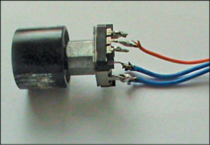
A 5-pin rotary encoder is shown in Fig. 2. Only three wires have been used for the project. The orange wire is the common lead, while blue wires are the two points, namely A and B.
Controlling stepper motor using rotary encoder
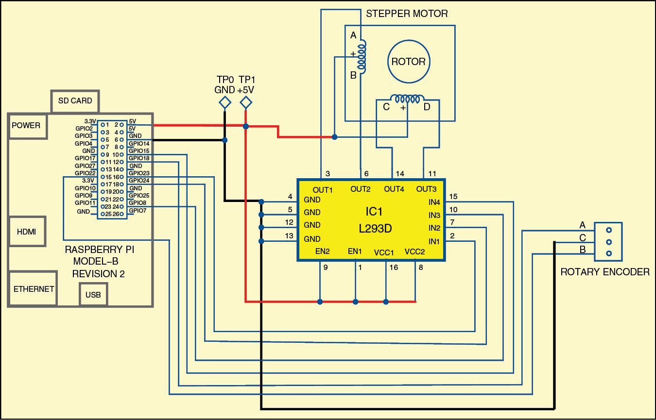
Circuit connection of the rotary encoder is shown in Fig. 3. The encoder is connected to physical pins 12 and 15, while the central (common) pin goes to ground pin 6 of Raspi.
The uni-polar stepper motor is connected to pins 16, 18, 24 and 26 (GPIO pins 23, 24, 8 and 7), and the common pin is connected to +5V of Raspi.
L293D is a quadruple half-H motor driver. The motor-enabled pin 1 and pin 9 are connected to positive supply pin 2 of Raspi. ULN2003, the Darlington array IC, may also be used for this project in place of L293D.
The actual direction control is done by running rotary-servo.php program in Raspi.
The initial set up of rotary-servo.php program is given below for reference:
[stextbox id=”grey”]require_once(‘GPIO.php’);
include(“wiringpi.php”);
$g[0] = new GPIO();
$g[1] = new GPIO();
$g[2] = new GPIO();
$g[3] = new GPIO();
$g[0]->setup(7, “out”);
$g[1]->setup(8,”out”);
$g[2]->setup(23,”out”);
$g[3]->setup(24,”out”);[/stextbox]
This program requires wiringpi.php library, which is available for download at github.com/WiringPi/WiringPi-PHP
First, install php5-dev before installing WiringPi as given below:
[stextbox id=”grey”]
sudo apt-get install php5-dev
[/stextbox]Now use git to install wiringpi.php
[stextbox id=”grey”]$ git clone https://github.com/WiringPi/
WiringPi-PHP.git
$ cd WiringPi-PHP
$ git submodule update -init
$ sudo ./build.sh
$ sudo ./install.sh
$ cp wiringpi.php /var/www/[/stextbox]
WiringPi is installed on Raspi and also copied to /var/www directory. But to get it inside PHP, load it in wiringpi.ini file.
Open wiringpi.ini file in /etc/php5/conf.d/ and write the following lines on it:
[stextbox id=”grey”]
$sudo nano /etc/php5/conf.d/wiringpi.ini
extension=wiringpi.so
wiringpi.pinmaptype=PINS
[/stextbox]Save the file and restart apache.
[stextbox id=”grey”]/etc/init.d/apache2 restart[/stextbox]
Download source code: click here
Run the following command to check whether WiringPi module has been loaded:
[stextbox id=”grey”]php -m | grep wiringpi[/stextbox]
After installing WiringPi for PHP, run rotary-server.php code, the main program of this project, by issuing following command:
[stextbox id=”grey”]$ sudo php –f rotary-servo.php[/stextbox]
Rotate the shaft of the rotary encoder in clockwise and counter-clockwise directions. You would see the stepper motor rotate in clockwise and counter-clockwise directions, respectively.
The article was originally published in Janury 2016 and has recently been updated.
