After you have successfully assembled the circuit, however, without invoking the IAR IDE tool and connecting a target board to the ParaFET, not much can be tested. The next section will describe building the target board for testing the working of the ParaFET.
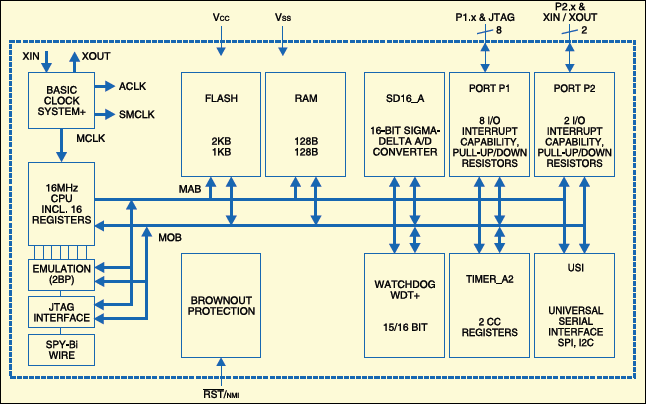
Now, we describe here construction of the target board to test the working of the ParaFET circuit. The internal block diagram of MSP430F2013 is shown in Fig.9.

Building the applications
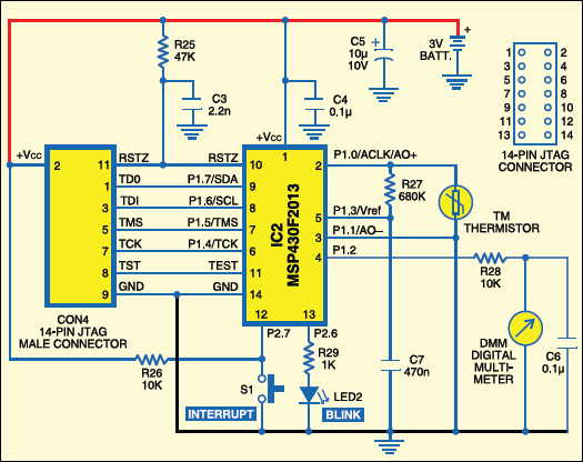
The target board combines two applications: a blinking LED and a precision digital thermometer based on MSP430F2013 chip. The circuit is shown in Fig. 10. (Refer to Parts List.)

To make you familiar with MSP430 programming and debugging, let us begin with a simple blinking-LED application. For this purpose, it is recommended to use a 3mm or 5mm LED which consumes less than 2 mA. Resistor R25 and capacitor C3 provide power-‘on’ reset to the MSP430. C4 and C5 are filter capacitors between VCC and GND. The connections include the TDO, TDI, TMS, TCK, TEST, RESET, +VCC and GND lines, which are terminated at the 14-pin JTAG connector (or FRC connector).
Software program
The Blinking_LED.c program is written in ‘C’ language can be downloaded from the link at the end of the article. The program starts with the msp430×20×3.h header file for MSP30F2013 device. This file is automatically picked up by the compiler from the IAR installation directory during program compilation. At the beginning of the program, the watchdog timer needs to be stopped. Otherwise, it will cause a non-maskable interrupt after about 32 ms.
Now, set up the clock system. By default, MCLK and SMCLK start off with the internal digitally controlled oscillator (DCO) at 1 MHz.ACLK has been programmed to use the internal very low-frequency oscillator (VLO), whose oscillation frequency is approximately 10 kHz. So there is no need to connect any external crystal.
Next, configure the port modules. The unused bits of port 1 are programmed as outputs with a value of zero. This ensures that stray voltages on this port don’t cause in advertent leakage currents. Port 2.6 is configured as the output to drive the LED through resistor R29.
Programming and debugging

The steps for programming and debugging after installing the IAR Embedded Workbench Kick Start for MSP430 in your system follow:
1. Connect the parallel port FET board (ParaFET) to the PC’s parallel port.
2. Connect the MSP430 target board to the 14-pin FRC connector from the ParaFET board.
3. Start IAR system from the desktop.
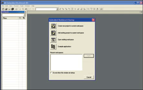
4. Select ‘Create New Project’ option from ‘Project’ menu (refer Fig.11).
5. Give a suitable project name, e.g., BlinkingLED.
6.Select ‘New File’ from ‘File’ menu. It will open up a blank document.
7.Copy and paste the blinking LED program to the blank document.
8. Right-click ‘Untitled’ tab and enter the file name with ‘.c’ extension, e.g., blinking_led.c
9. In the left window pane, right click the project name and select ‘Add’ option to include ‘blinking_led.c’ program.
10. Right-click the project name and select ‘Options’ (refer Fig. 12).
11. Left-click the square button next to the text box containing ‘Generic MSP430 Device’ and select ‘MSP430F2013.’
12. Click ‘Library Configuration’ and select ‘Normal DLIB’ for library option.
13. Click ‘Library Options’ tab and select ‘Tiny’ for printf formatter and ‘Small’ for scanf formatter; these settings ensure small size of the compiled ‘C’ code, which is appropriate for the applications given in this article.
14. Click ‘ok.’
15. Again, right-click the project name and select ‘Debugger’ from ‘Options’ pull-down menu. Here, you can choose between simulator and FET debugger options.
16. Select ‘Simulator’ to simulate the program in software and ‘FET Debugger’ to download the program using ParaFET to the target board in order to program the MCU and do an in-circuit emulation. Ensure that the FET debugger is either Texas Instruments LPT-if or just parallel-port-if.
17. Invoke the simulator/debugger by clicking the icon shown in Fig. 13.
18. On clicking the debug button, the IAR will compile the program and give a message saying that it is erasing the flash and downloading the program. If the program download is successful, the debugger environment comes up. Now, the program is ready to run on the target board.


