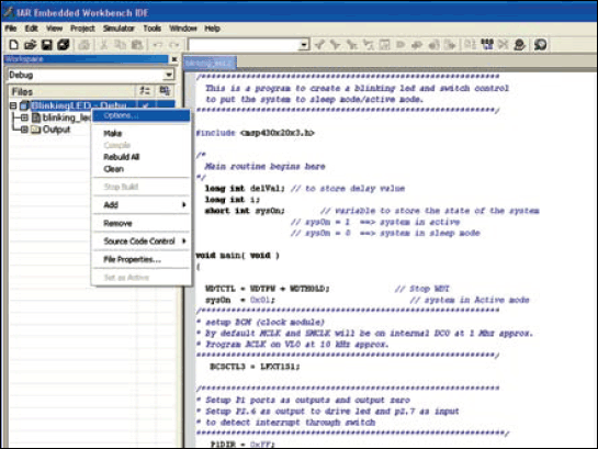
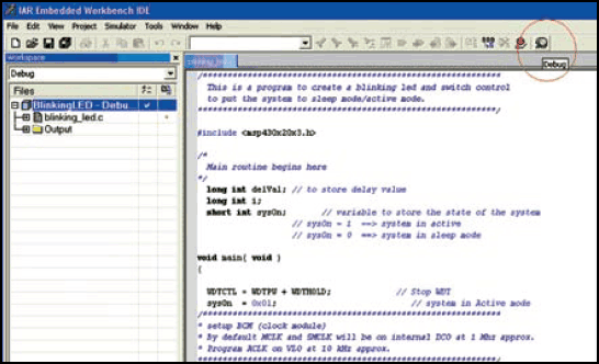
19. Remove the ParaFET circuit and test the blinking of the LED. The LED should blink with ‘on’ and ‘off’ durations of about one second each.


Tips
1. Ensure that the target board is not connected to the battery when it is connected to ParaFET.
2. USB connection is not required for the blinking-LED application. However, it is required for digital thermometer program.
3. After ensuring that the program is working correctly, disconnect the target board from ParaFET and connect the external battery. The target board should work off the external 3V
battery.
After successfully testing the LED blinking application program, you can proceed to the digital thermometer application. Repeat the above steps for digital thermometer program.
The CPU itself works off an internal oscillator, so there is no need to connect an external crystal. The high resistance (82-kilo-ohm) thermistor keeps the system power consumption low and also makes the error quite negligible. It is connected to 1.2V (Vref) internal voltage reference pin 5 (p1.3) through resistor R27 (680-kiloohm). We recommend use of a metal film resistor for linearity and precise output. Metal-film resistor has better temperature characteristics and current- noise suppression level. It is good to measure the value of this resistor and note down before soldering it, as this value can be used in the program to improve accuracy.
Designing a low-cost precision thermometer
Here we describe a simple add-on circuit for a digital multimeter that enables direct read-out of temperature with fairly high degree of accuracy. Designing with MSP430 microcontroller
results in low cost, low power consumption and high precision of the application.
The circuit is designed for use with a commonly available 82-kilo-ohm thermistor bead. A digital voltmeter is connected to the board to read out the temperature directly. For example, a value of 10°C is displayed as 100 mV, 25.6°C is displayed as 256 mV and so on.
The CPU itself works off an internal oscillator, so there is no need to connect an external crystal. The high resistance (82-kilo-ohm) thermistor keeps the system power consumption low and also makes the error quite negligible. It is connected to 1.2V (Vref) internal voltage reference pin 5 (p1.3) through resistor R27 (680-kilo-ohm). We recommend use of a metal-film resistor for linearity and precise output. Metal-film resistor has better temperature characteristics and current-noise suppression level. It is good to measure the value of this resistor and note down before soldering it, as this value can be used in the program to improve accuracy.
Capacitor C7 (470nF) is used to filter noise on reference voltage pin 5. The voltage across the thermistor is measured using the differential voltage on pins A0+ and A0- of ADC channel 0. This method of measurement also helps in rejecting any common-mode noise that the thermistor leads might pick up.
The temperature output is available at pin 4 of the MSP430 MCU. It is fed to the digital multimeter through an R-C filter formed by resistor R28 and capacitor C6.
The JTAG pin connections are brought out to a 14-pin FRC connector which is used for flash programming and debugging. Push-to-on switch S1 is used to generate a trigger to the system to toggle the system state between active and power-down modes.
Thermistors are highly non-linear components whose resistance decreases with increase in temperature. It has a negative temperature coefficient. Thermistors are good in that these are very sensitive to temperature changes and quite inexpensive. However, their resistance vs temperature characteristic is highly non-linear. Hence normally it requires complex signal conditioning to measure the temperature accurately. It is exactly in this respect that the circuit becomes versatile as the non-linearity of the thermistor behaviour can be easily compensated in software. Here, it is assumed that the user has characterised a thermistor and therefore has a lookup table of resistance vs temperature readily available.
The formula to measure the thermistor resistance is derived as follows:
Voltage across the thermistor
![]()
where R1 is the reference resistor (680-kilo-ohm), Vref is the internal voltage reference (1.2V) and Rt is the thermistor resistance at a given temperature.
From Eq. (1), we can obtain thermistor resistance:
![]()
Using the lookup table, consisting of characterised values of resistance vs temperature, along with a linear interpolation technique, you can get the equivalent temperature with a fairly high degree of precision.
Next, convert this value into a precisely scaled PWM waveform such that the average value of this waveform, in volts, is equal to the temperature measured in °C. As the PWM waveform swings between ground and VCC, the average value is dependent on VCC. In this case, since we are using a battery without regulation, VCC changes over time as the battery discharges. Hence the program measures the battery voltage periodically and always uses this value to create the right PWM waveform. Thus a simple PWM is used to generate an accurate digital read-out on the multimeter over the entire lifetime of the battery.
Thermometer program
The digit_thermo.c thermometer program is written in ‘C’ language. It can be downloaded from the link at the end of this article. Here is the outline of the program.
After the initial variable declarations comes the res_temp_lookup table, containing the resistance vs temperature values. About 99 values are present in this table to cover the temperature range from 0°C to 100°C accurately. The get Tem DegC function is defined to fetch the correct value of temperature for a given thermistor resistance after interpolation between adjacent entries in the table.
The clock system is programmed to run both MCLK and SMCLK on the internal DCO at 2 MHz. ACLK runs on VLO. Ports P1.0, P1.1 and P1.3 are programmed to ensure proper ADC connectivity. ADC registers are programmed to use SMCLK.
The timer is set up such that it generates a 2kHz PWM waveform on port 1.2, which is fed to the digital multimeter. Switch S1 takes the system to sleep mode or to active mode.
Variable sysOn is used as a flag to indicate the state of the controller system. This flag is toggled whenever an interrupt is generated using switch S1. The sysOn has a value ‘0’ when S1 is pressed momentarily. When sysOn is ‘1,’ the system will be in active mode and keep measuring the temperature. When sys On is ‘0,’ the system will be in sleep mode.
Even in active mode, the system normally enters low-power mode 1 (or LPM1 mode), where MCLK and the CPU are ‘off’ but SMCLK and ACLK are running. SMCLK is needed to keep the PWM output active to enable continuous reading of the temperature.
The watchdog timer is programmed to wake-up the system approximately every second. On wake-up, the system measures VCC value and the thermistor resistance through the ADC channels. The resistance is converted into temperature. These values are used to set up an appropriate duty cycle on the PWM waveform whose average value equals temperature in °C.
Note that this system consumes about 500 μA of current when measuring and displaying temperature. This means that it will work for more than 300 hours continuously with a CR2032 (3V lithium cell). In sleep mode, the system consumes just about 0.1 μA. Hence the battery will last longer for intermittent temperature measurements. Additionally, the low sleep mode current eliminates the need for a separate power switch as the system can be put to sleep mode without worrying about draining the battery.
Construction
Combined actual-size, single-side PCB layout for the blinking LED and thermometer is shown in Fig. 14 (View as PDF) and its component layout in Fig. 15 (View as PDF). Note that the PCB has a provision for connecting an LED, though it is not used in the thermometer program.
Download PCB and component layout PDFs (Fig. 7,8,14,14,15): click here
You may visit the www.ti.com/msp430 to get access to all the datasheets, user guides, application notes, example codes and development tools pertaining to the MSP430 chip.
Download source code: click here


