 When we do not drive our cars for extended periods of time, the abandoned rechargeable batteries become fully discharged. Sometimes, these get damaged, too.
Batteries have self-discharging rates that depend on their type and capacity, and may vary from a few milliamperes to tens of milliamperes. Also, the electrical installations in a car have leakage currents that may discharge the battery. If we compensate the discharging current, the battery will remain always charged. This can reduce the probability of the battery getting discharged or damaged. In any case, it is good to read the datasheet of the manufacturer in order to know how to maintain the battery.
Circuit and working
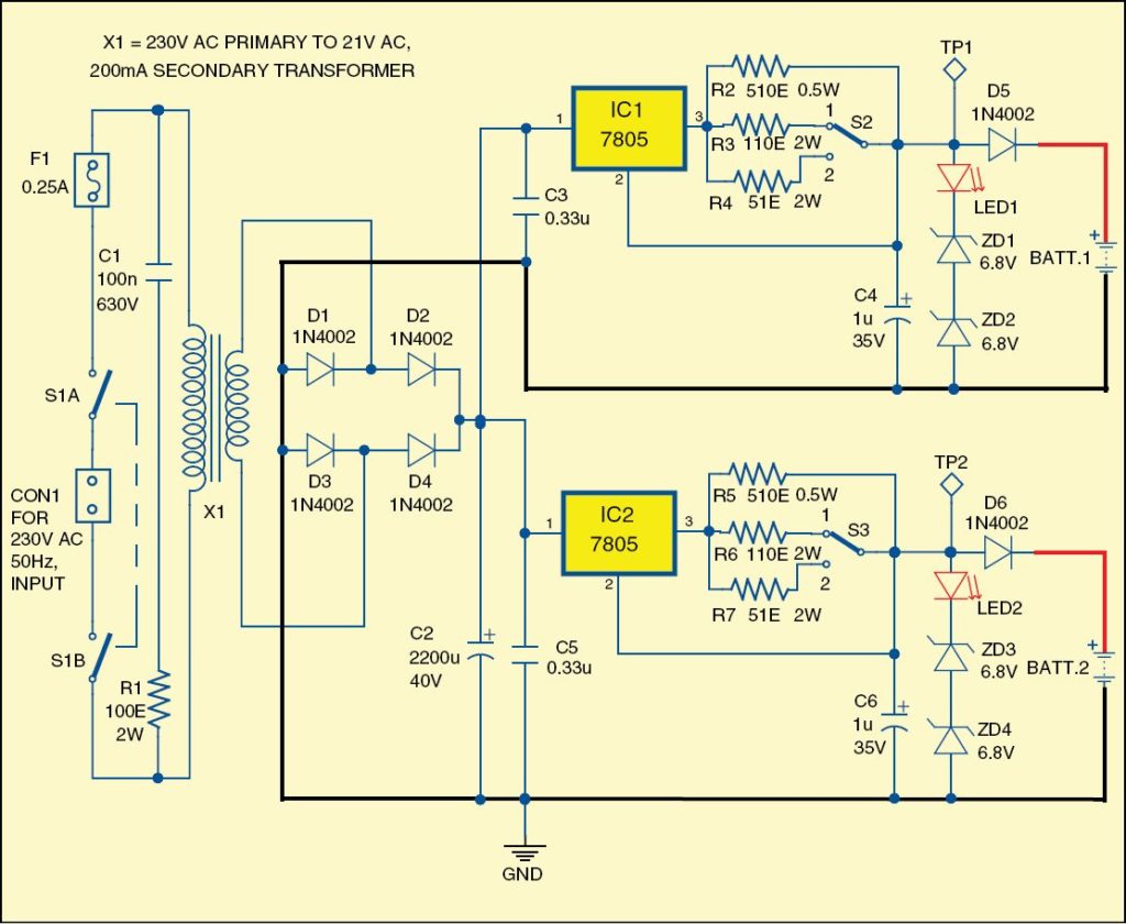
Fig. 1 shows the simple device that can maintain two 12V rechargeable batteries. The mains power supply is applied to connector CON1 and is reduced by transformer X1 to 21V AC, 200mA. The bridge rectifier comprising diodes D1 through D4 rectifies the AC voltage.
The device has two identical channels. Each channel has an individual low-cost linear regulator 7805 (IC1 and IC2). The minimum output current for the battery is set by resistors R2 and R5 at around 10mA. The maximum output current can have two values (around 50mA and 100mA).
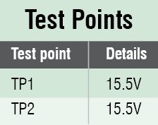
When switches S2 and S3 are at position 1, the output current is around 50mA. When switches S2 and S3 are at position 2, the output current is around 100mA. The maximum output voltage is limited to around 15.5V with LED1, ZD1 and ZD2 for the first channel and LED2, ZD3 and ZD4 for the second channel.
Raising the current to around 100mA should not damage LED1 and LED2. Diodes D5 and D6 prevent the discharge of batteries BATT.1 and BATT.2 when the mains power supply is not present. Nevertheless, if the mains power supply is not present for a long time, disconnect the batteries from the device.
Mount regulators IC1 and IC2 on small individual heat-sinks with thermal resistance below 30°C/W. The device will start working immediately if the circuit is wired properly. Verify the maximum output voltage and maximum output current with a multimeter.
Construction and testing
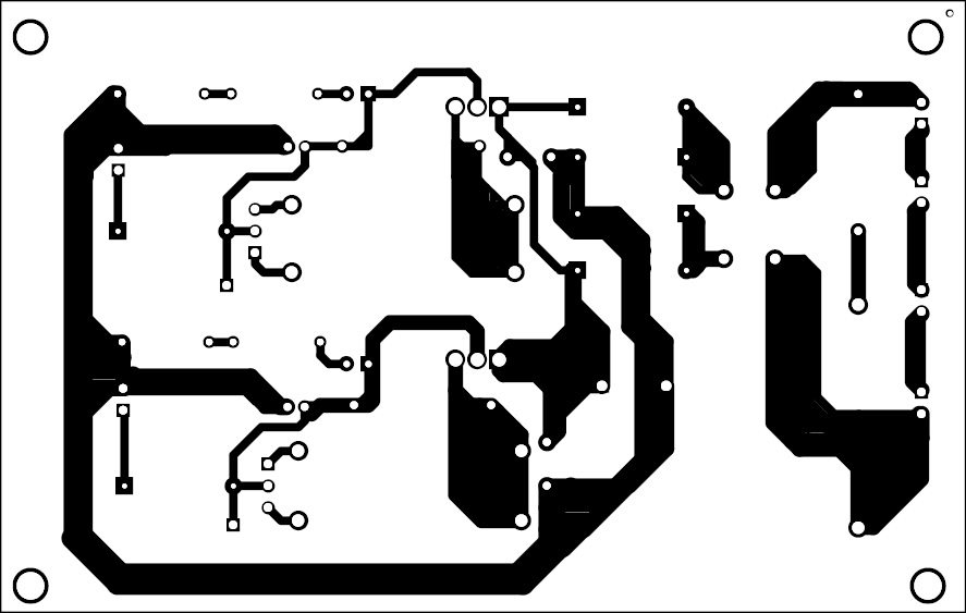
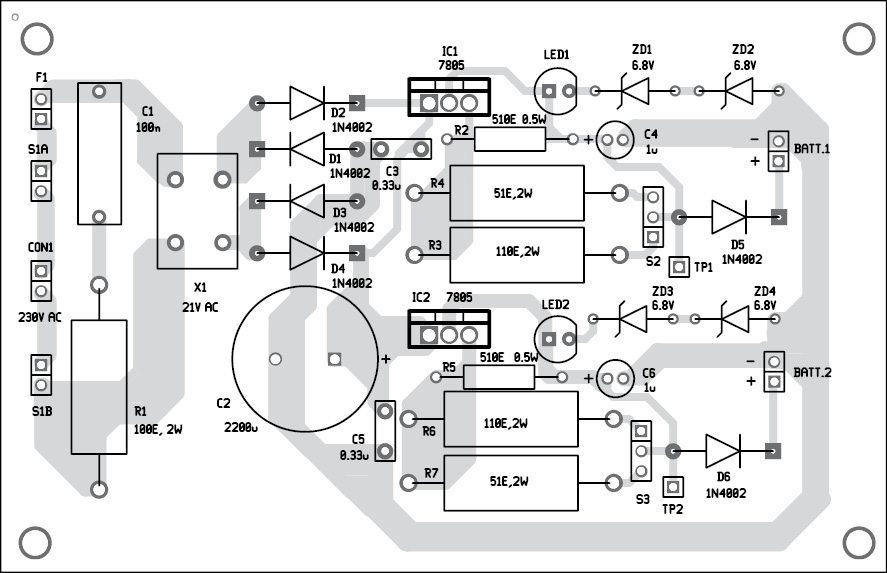
A single-side PCB for the power supply is shown in Fig. 2 and its component layout in Fig. 3. Enclose the PCB in a suitable small box in such a way that outputs can be easily taken from the front panel.
The ground pin of each 7805 IC is connected to the metallic part of the package and, consequently, the metallic part of at least one of the ICs should be isolated from the common heat-sink. Panel-mount AC input, switches, fuse, output connector and battery, as per requirement.
Download PCB and component layout PDFs: click here
Petre Tzv. Petrov was a researcher and assistant professor in Technical University of Sofia, Bulgaria, and expert-lecturer in OFPPT (Casablance), Kingdom of Morocco. Now, he is working as an electronics engineer in the private sector in Bulgaria


Dear Petre Tzv. Petrov,
Today, sunday 4/3/2016, i have encountered this circuit, in my opinion, it’s quite useful and applicable. However, there is something in my mind preventing me from fully understanding. Could you please demonstrate me some more? It’s about IC 7805, a voltage regulator of narrow down the output to 5v, that’s what i get in my mind for so long. In your circuit, the output is 15.5V? I’m not quite sure of it.
Your sincerely,
Here’s the reply from author
Here’s the reply from Petre TZV Petrov.
“7805 works here as current generator. It does not work in its classical application of series regulator with 5V output between the output of the regulator and the ground of the circuit. Please see the data sheet of 7805. The output current of IC1 is set with R2, R3 and R4. The output voltage over the battery 1 (BAT1) is limited by the series network of LED1, ZD1 and ZD1. You can use any appropriate combinations of LEDs, diodes, Shottky diodes and Zener diodes to limit the output voltage to the requited value. The maximal output voltage over BAT1 is approximately the input voltage over C3 reduced with about 8.2V, as follows:
-around 2.5V over the 7805
-5V over the resistors R2, R3 and R4.
-around 0.7V over D5
The circuit is very simple and it works immediately after the proper montage is done.”