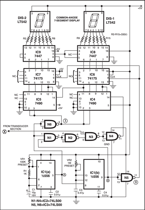
This digital speedometer displays the speed of the vehicle in kmph. An opaque disc is mounted on the spindle attached to the front wheel of the vehicle. The disc has ten equidistant holes on its periphery. On one side of the disc an infrared LED is fixed and on the opposite side of the disc, in line with the IR LED, a phototransistor is mounted. IC LM324 is wired as a comparator.
Digital speedometer circuit

When a hole appears between the IR LED and phototransistor, the phototransistor conducts. Hence the voltage at collector of the phototransistor and inverting input of LM324 go ‘low’, and thus output of LM324 becomes logic ‘high’.
So rotation of the speedometer cable results in a pulse (square wave) at the output of LM324. The frequency of this waveform is proportional to the speed.

Calculations
Let ‘N’ be the number of pulses in time ‘t’ seconds and numerically equal to the number of kilometres per hour (kmph). For a vehicle such as LML Vespa, with a wheel circumference of 1.38 metres, and number of pulses equal to 10 per revolution, we get the relationship:
N pulses/ t = N kmph
= Nx1000 / 3600×1.38 metres per second
= Nx1000x10 / 3600×1.38 pulses per second
Therefore, time ‘t’ in seconds = 0.4968 second.
Circuit construction

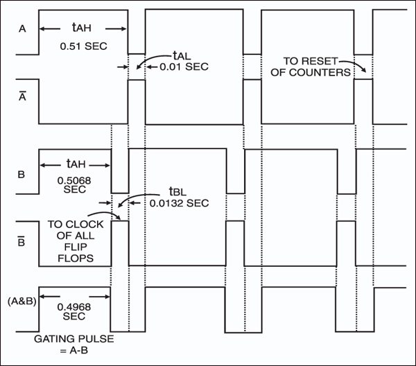
As shown in the timing diagram, at t=0, output of astable flip-flop IC1(a) i.e. ½556 goes low and triggers monostable multivibrator IC1(b) i.e. ½556. Pulse width of monostable IC1(b) = 0.5068 sec. For IC1(a), t(on) = 0.51 sec. and t(off)= 0.01 sec. The outputs of IC1(a) and IC1(b), and the signal from the transducer section are ANDed. The number of pulses counted during the gating period (0.4968 sec.) is the speed N in kmph (kilometres per hour).
Circuit operation
At the end of the gating period, output ‘B’ of monostable IC1(b) goes low and B goes high. The rising edge of B is used to enable the quad ‘D’ flip-flops IC6 and IC7.
At this instant, i.e. at t=0.5068 sec., the number (speed) N will be latched corresponding to the ‘D’ flip-flops and displayed. At t=0.52 sec., output of astable flip-flop IC1(a) goes low and remains low for 0.01 sec. This waveform is inverted and applied to the reset terminals of all counters (active high).
Thus the counters are reset and counting begins afersh at t= 0.53 sec. up . However ‘D’ flip – flops are not enabled and previous speed is displayed. The new speed is displayed at t=0.52 + 0.5068 sec. In this way the speed will be updated every 0.52 sec.
Testing
This speedometer can measure up to 99 kmph with a resolution of 1 kmph. The range can be increased up to 999 kmph by adding another stage consisting of one each of ICs 7490, 74175, 7447 and a 7-segment display. The voltage supply required for the operation of the circuit is derived from the vehicle power supply (12V).
The calculation shown above are for LML Vespa and Kinetic Honda . The calculations for using this speedmeter for Yamaha , whose circumference of wheel = 1.8353m , can be obitained in a similar fashion. The gating period will simply vary in direct proportion to the wheel diameter. It will be 0.6607 sec. for yamaha.
The same speedometer can be used other vehicles by making similar calcualtions. In all the calculation it has been assumed that the speedometer cabel makes one revolution for every revolution of the wheel of the vechiles. Note that on / off periods of the wave- forms have to be practise. High quality multiturn pots and low temperature coefficient componenets should be used in the timer ICS.
Feel interested? Check out other electronics projects.


Ok tested low cost very simple circuit diagram for training student please never forget it I’m waiting for your email thank you
Sir very very thankful to you for your kindness
I have to required a list 0f yourproject diagram within cost of RS 150/ only if satisfied then take more
Please elaborate your query.
i don’t understand, what is the function of speedometer cable ? thanks
may i have more details on this circuit? Because it is not working as it should be for my case.
Kindly elaborate your query.
I implemented this with manual soldering method in 2007 from this site page only. It was partially successful bcoz of personal capability. I was not aware of printing circuit on board. I love this project, it was very new then. I always want to this again for my interest. Thanks to efy and author.
I can’t understant circuit diagram. Please send circuit diagram clearly.
Dear sir/ man,
Your information was really good for me.but how reprogram the ic chip ..
Can u please guide me. Plz send me mail on that regards.
Please can you give more detail with regard to the calculations please? I do not understand why N is multiplied by 1000, then divided by 3600. Surely N is a variable linked to the speed the disc is rotating?
Dear sir,
Requesting yourself to send me a diagram of Suzuki access 125 digital speedometer for easy repairing and your crucial tips for simpler rectification for the same .
Thanks
Sanjay Mohit
7977993668
[email protected]
i want to know about this digital speeedometer brand
Hi Muhammad, this is a circuit system for constructing your own Digital Speedometer.