 This simple door opening alarm using hall sensor produces sound when someone opens the door. The circuit can be installed at a workshop, office or home for security purposes. The 3-terminal hall sensor is easily available in the market.

Door opening alarm using hall sensor circuit
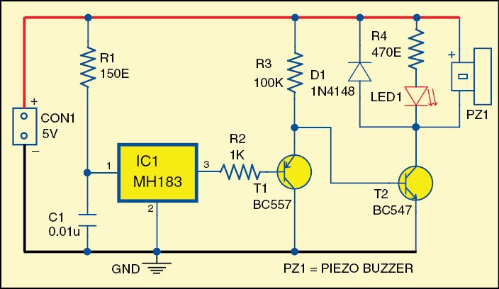
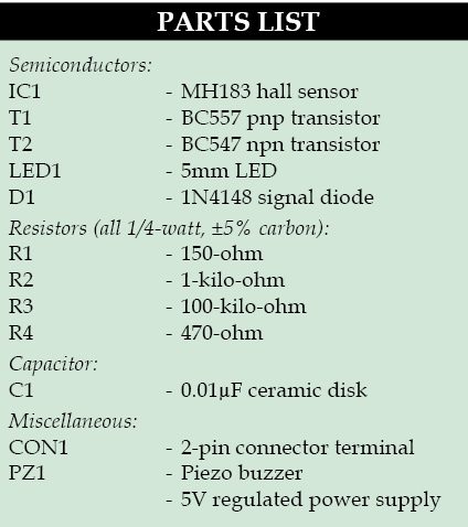
The circuit diagram of the door opening alarm is shown in Fig. 1. It is built around hall sensor MH183 (IC1), pnp transistor BC557 (T1), npn transistor BC547 (T2) and a few other components.

Hall sensor MH183 is a magnet-operated solid-state sensor. When the magnet is brought near the sensor, its output goes low. This low output is amplified by pnp transistor T1. npn transistor T2 inverts the operation. When T1 conducts, T2 does not conduct, and vice-versa.

The magnet should be fitted on moving part of the door and the sensor at the door frame. When the door is closed, the magnet comes close to the sensor and the alarm is off. But when door is opened, the alarm makes a sound.
The buzzer can be replaced with a 5V relay to control a mains alarm.
When the door is closed, neither the buzzer sounds nor LED1 glows. But when the door is opened, the buzzer sounds and LED1 glows, too.

Construction and testing
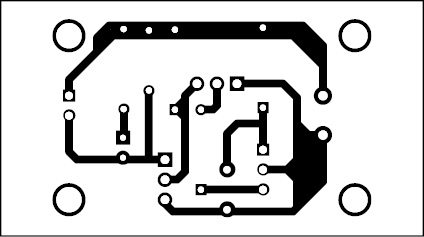
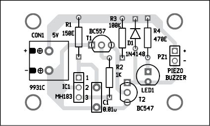
An actual-size, single-side PCB for the door-opening alarm circuit is shown in Fig. 2 and its component layout in Fig. 3. Enclose the PCB in a suitable small box and install it at a suitable place.
Download PCB and component layout PDFs: click here
Fit the magnet on a moving part of the door and sensor MH183 on the door-frame opposite to it.
Use 5V regulated power supply for the circuit.
Feel interested? Check out other electronics projects.


Cannot find the “MH183” hall sensor anywhere online.
It is available in Flipkart’s
You can buy from this link: http://www.rhydolabz.com/magnetic-rpm-c-137_149/hall-effect-sensormh183-unipolar-p-391.html
how come the downloadable “PCB and component layout PDFs” is different from the one in the images. I am currently trying to build a door alarm with a timer supplied with 240V would it be possible to use this in order to get it done?
Thank you for your comment. We have updated the article with correct PCB and component layout PDFs. Please check.
thank you for the update, I only have a question regarding am addition, if I wanted a 20-second delay before the piezo buzzer is on, what would be the best way to do that?
Thank you.
how can i get the whole pdf document of the project