The circuit described here is of a dual audio signal tracer. An audio signal tracer is a simple device used to troubleshoot for audio signals in radio and other electronic circuitry.
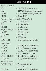
The device is a battery-powered stereo amplifier with two loudspeakers, packaged into a small handheld unit with test probes. An optional diode detector can be incorporated for the detection of amplitude-modulated signals. A test signal (audio) is injected into the tracer at CON1/CON2 from various points of the circuit under test. So long as the signal is heard, the circuitry up to that point is (at least minimally) functional. However, if the signal disappears, a fault can be assumed to be present in the stage of the circuit just preceding it.

The simple external diode detector is not only sensitive to amplitude modulation but even circuits that are normally used for other modulation schemes (such as FM radios) can be tested in some cases.

Dual audio signal tracer circuit
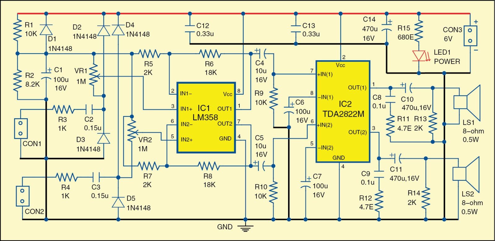
Fig. 1 shows the circuit diagram of the dual audio signal tracer. It is built around LM358 (IC1) and TDA2822M (IC2). LM358 has two independent, high-gain, internal-frequency-compensated operational amplifiers, which are designed specifically to operate from a single power supply over a wide range (3V to 32V) of voltages.
TDA2822M is a low power stereo amplifier. Its outputs can be directly coupled with the speakers through decoupling capacitors. The tracer is sensitive enough to capture signals from most microphones.
The relatively high input resistance of 1-mega-ohm (VR1 and VR2) makes it possible to capture audible signals from many tone-control circuits and filters. Input signals are applied to connectors CON1 and CON2 and amplified by the two amplifiers in IC1.
Both amplifiers (channels) are completely independent. Resistor R3 and diodes D2 and D3 protect the input of the first amplifier. Similarly, resistor R4 and diodes D4 and D5 protect the input of the second amplifier. Resistors R1 and R2, diode D1 and capacitor C1 provide the necessary bias DC voltage for the operational amplifiers in IC1.
Potentiometers VR1 and VR2 adjust the volume for the first and second channel, respectively. Op-amps of IC1 are configured as non-inverting amplifiers with gain fixed at ten. Voltage gains can have any values starting from one, depending on the need. However, it is not a good idea to have voltage gains higher than 30 because then the circuit becomes too sensitive to electromagnetic fields and may produce a lot of noise in the loudspeakers.
IC2 works as a dual-channel output amplifier. Each amplifier works with internally-fixed gain of around 100. The amplifier can drive loudspeakers and headphones with resistance equal to or higher than 8-ohm.
Download PCB and component layout PDFs: click here
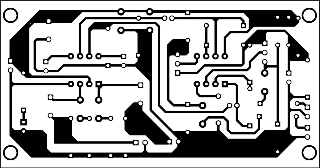
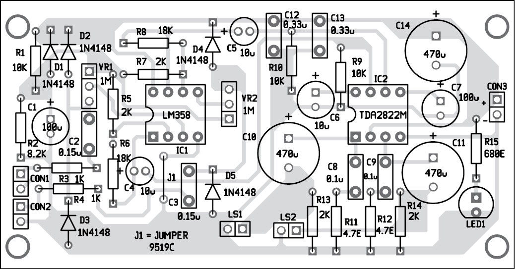
Construction and testing
A single side PCB of the dual audio signal tracer is shown in Fig. 2 and its component layout in Fig. 3. After assembling the circuit on a PCB, enclose it in a suitable plastic box.
The circuit works well off 6V battery; the preferred power supply is 6V and above. The circuit is appropriate for the signal tracer, as general-purpose dual audio amplifier and as low-power stereo amplifier. The output power can reach 1W over 4-ohm with 9V power supply, which is more than enough for listening to the produced sound in a small room.
The article was originally published in February 2015 and has recently been updated. Feel interested? Check out other electronics projects.