Solar energy is coming up as a major source of energy. The need of the hour is renewable energy resources with cheap running costs. With the current systems for solar energy harvesting, we have high production only at fixed times mostly noon. This project proposes a dual axis solar tracker system that increases the productivity by a significant margin.
Solar Angles
The angle of inclination ranges between -90° after sun rise and +90° before sunset passing with 0° at noon. This makes the collected solar radiation to be 0% at sunrise and sunset and 100% at noon. This variation of solar radiations collection leads the photovoltaic panel to lose more than 40% of the collected energy. In this project, we take you through designing a Solar tracker so that you maximise on the solar energy collection.
Designing the Dual Axis Solar Tracker system
This system requires involvement of a wide range of engineering including mechanical electrical and electronics. The system can be broken down into these three domains as well.
The mechanical part would involve designing a smooth gear system to move as per requirement. The electrical part would be the working of solar panel and battery requirement. The electronics would involve designing the sensor system that would generate commands for the gear system to act accordingly.
Electronics component list:
| S.No. | Component | Quantity |
| 1 | Transformer step down 12-0-12 | 1 |
| 2 | Voltage Regulator 7805 | 1 |
| 3 | Transistor npn | 4 |
| 4 | Diode | 2 |
| 5 | Capacitor | 3 |
| 6 | Variable Resistor | 4 |
| 7 | Light dependent resistors (LDR) | 4 |
| 8 | Microcontroller 89S52 | 1 |
| 9 | Motor driver uln2003a | 2 |
| 10 | Solar Panel (all black) | 1 |
| 11 | Unipolar stepper motor | 2 |
| 12 | Crystal oscillator 12 Mhz | 1 |
The system employs spur gear for the implementation of the dual axis solar tracker.
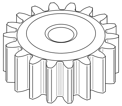
A spur gear is a simplest type of gear and can be seen a lot of applications including clocks and escalators. It consists of teeth protruding perpendicular to the circumference of the wheel.
For the dual axis rotation we propose the arrangement mentioned in the diagram below.
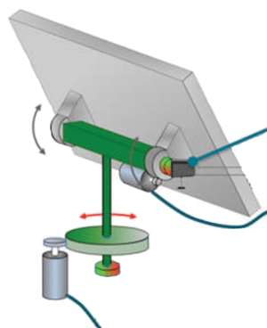
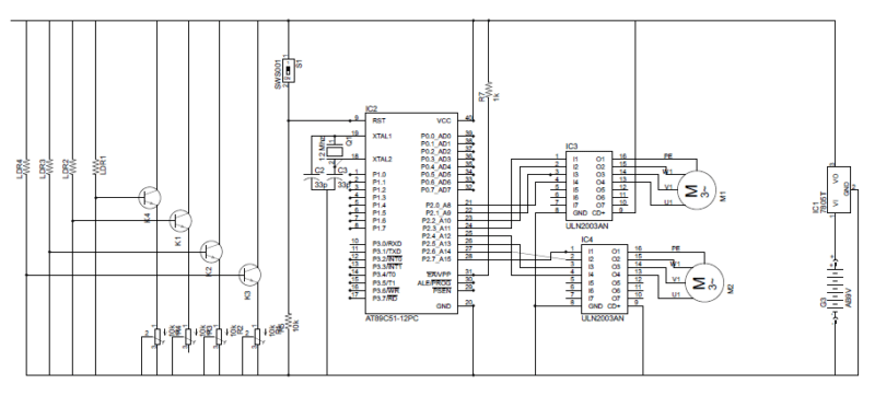
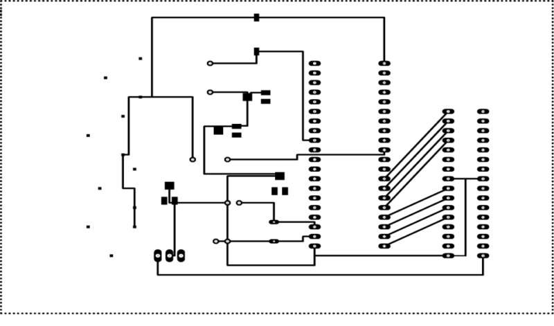
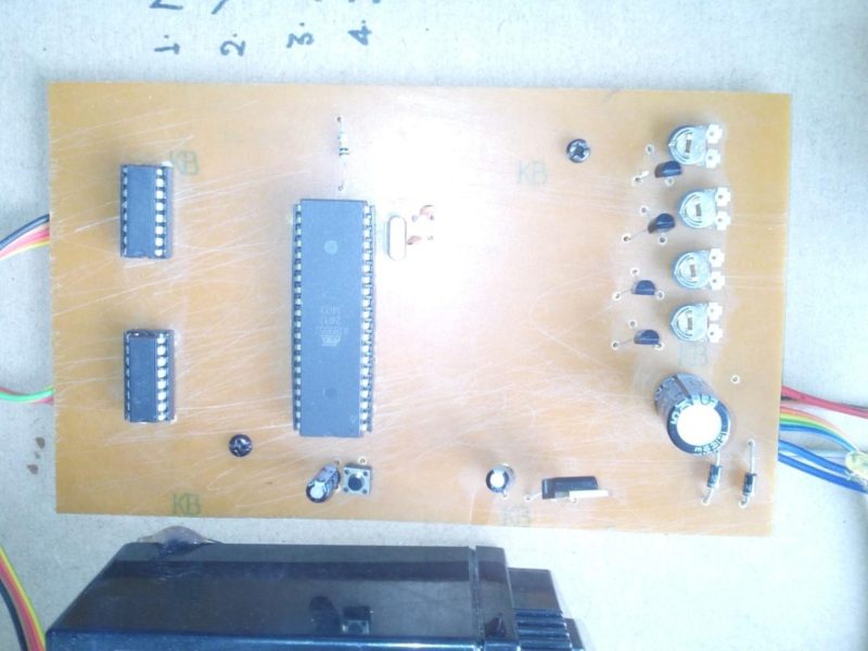
The system is implemented using Atmel IC AT89C51. The circuit design for the system would be:
![]()
Final Results
Dual Axis Solar Tracker project is to provide an efficient solar distributed generation system. At maximum, the solar tracker is perpendicular to the light source. The built system has a calculated annual energy gain of 48.982% compared to an immobile solar panel. Compared to a single axis tracker, the dual-axis tracker has an annual energy gain of 36.504%.
The purpose of a solar tracker is to accurately determine the position of the sun. This enables solar panels interfaced to the tracker to obtain the maximum solar radiation. With this particular solar tracker a closed-loop system was made consisting of an electrical system and a mechanical system with the help of electronics.
Feel interested? Check out other electronics projects.


This project does not explain how to identify the position of the sun and position the panel perfectly.
The point of a solar tracker is to track the sun automatically and align itself. All you need to do is place it on a level surface.
It is better also to track the maximum power from the solar radiation
do you have the used code for this project…. can u message me on my facebook account Jed Jed
.. [email protected]
i want to forward the project via email
Hi luise, you can mail your project at [email protected].
forward it to me also @ [email protected]
please forward the code to [email protected]
Will wait for your help, thanks friend
can u forward this project details with codings via mail to [email protected]
please forward the project and the code to :
[email protected]
Can you send this project to us
please can you mail me the project details and report at [email protected]
forward it to me also. thank you
[email protected]
[email protected].. If u can send me it will be helpful for my final year minor project… Plzzz
hi luise can you please forward me the details and coding of this project? [email protected]
can you please forward me too.
my gmail id is [email protected]
can you plz share it in my mail too [email protected]
do you have the used code for this project
forward to me via email [email protected]
forward it to me also @ [email protected]
forward to me
Can any one tell me the code of this project
Can u say brief about the project or plz send this project details to my email.. .
Plz say cost of this project?
Plz Forward to my mail [email protected]
Plz give full project with code
how much torque for the motor??
Please Forword to me my mail [email protected]
Sir please can u send me PDF file of it ..
From beginning to end of project..
[email protected]
Plz sir send me the whole project through email
[email protected]
Hi sir,
can u give me full project details with cost and code etc. on my email.
thank you sir.
Email:- [email protected]
plz sir send fast as soon
email me the complete project please
[email protected]
Pls sir send me the hole project through email [email protected]
Please can I get a C or C+ language code for project? And I’ll also love to have the project sent to ma email [email protected]. Thank you
sir please send me whole project in details. i want to do it in my college
techfest so i need complete details about it.
[email protected]
sir please send me project source code
[email protected]
sir please send me whole project in details. i want to do it in my college
tech-fest so i need complete details about it.
Please send me the codes here [email protected]
Friends, hello, do you have the code for this project? Would you please send it to me? [email protected]
hi sir, can you send me the code of this project sir and also the link regarding the process to make the project.
my email id is [email protected]
Will you plz send me the code of this project
hllo sir, i don’t know what u saying in this project,
send me the project plz.
my mail i’d is [email protected]
Send me complete project details on – [email protected]
please forward the project and the code to :
[email protected]
Hi Ghader, All the information related to the project are already present in the article.
how to make this project plz send me vedio
[email protected]
I made a simple and small dual axis solar tracker. here is the link below.
https://www.youtube.com/watch?v=7076aoRs1vs&t=31s
If you need any help regarding the project email me at : [email protected]
Cost?
Step by step assembly?
Parts’ more details?
If any mechanical engineer ready to do..I will sponsor expense
Pune based …
[email protected]
please sir can you help me with the full project details including costs
please sir can you mail me code for this project at [email protected]
please sir can you mail me code for this project at
[email protected]
forward it to me also @ [email protected]
please forward the project to me also at [email protected]
What is the torque of unipolar stepper motor you used
Please give details about this project at my email.l faced some problems in this project please help me
Please give me details about gear measurements example : angle,pitch, thickness etc
Please please send me on my email
[email protected]
please give me project my email= [email protected]
send me project
please forward the details about the project. Details about whole procedure-how to do it to [email protected]
Sir please sent me this hole project. details about this fantastic project [email protected]
Can I take all this project
I need this for my graduation project
I need the code and the program used it
And circuit design
And system building
Plz frward project details and code and full pdf [email protected]
I was just wondering what code you used for this and how did you go about designing the gear for it to move? If you could email me the details? That would be greatly appreciated, I’m designing a solar panel for camping in the summer time and being able to hook up a trailer and it would be great to have an idea of how to put this together. [email protected]
Hi,
nice project, I can get code for IC. I want to build it. Thank you, Peter
nice project
Hello sir, please send to me this project n code
Hi Mohd andrian, this is a Guest article. The author has not provided the source code of the project.
sir i need this project details can u mail me sir :- [email protected]
so first it is good project idea for improving maximum efficiecy
sir plz may u send pdf of this poject
Sir,
What are the value ofDiode and capacitors
So awesome…please send to me this project through my email.
Plz give full project with code
I would like the full details of this project to be sent to me.
This is awesome!
sir,
can u give me full project details with cost and codes, circuit diagram, components details and may be with video and any other details that can assist me in implementing this project, I would like it for my college project.
thank you sir.
awesome project sir.sir can you share videos of your project
sir can you please provide me with all the project details such as code and step by step information as early as possible at [email protected]
Hey Luise , I am interested in your project. May you please forward it to my email: [email protected]
Hey Luise, I am also interested in your project. Can you please forward the project to my email:
[email protected]
Hi Mian Idrees,
You can save the project on your PC via save as PDF or webpage.
Bro, i’m asking for microcontroller programing code
Can you please share the details of the project as soon as possible to [email protected]. I will be so thankful to you!!
Sir,
Thank you for the useful project.
1. Which controller should I use? In the BOM it is mentioned as 89S52. But the circuit and description mentions AT89C51.
2. There are 3 capacitors mentioned in the BOM. But I am unable to locate the third capacitor.