 I have an old window AC in my lab, which is at the terrace. The AC needs to be run intermittently, especially when I am out of station and the lab PC needs to be kept cool during noon time when the temperature shoots to 35+ degree centigrade, irrespective of summer or winter. Of course, the AC’s thermostat works, but it needs to be adjusted continuously—else it will keep running for prolonged periods during summers, which I want to avoid.
The following timer based on Arduino does exactly that. I can set the on-time and off-time based on the entire calendar timings! It is based on a simple DS3231 real time clock (RTC) timer, an ATMEGA328 Arduino chip, and a small 5V relay to run the 5kW contactor that controls the AC.

Trigger to go further
“Uncle you have made a whole calendar-dependent timer, but you are not showing clock/calendar, or the alarm time, etc, anywhere. It should display time at least to know what it’s going to do next, or what it has done so far,” my friend’s son Reon declared as his first impression.
The whole can of worms got spilled out when I failed to comply miserably to his request! For running the on-time and off-time, I had used switch statements combined with ‘if’ statements in DS3231_AC_Scheduler.ino Arduino code. Therefore, the clock necessarily stopped inside the ‘if’ loop. Only when the ‘if’ statement expired the loop ended, the clock started, and the next ‘switch’ statement was executed. Therefore, the clock display ran intermittently with this sketch when it executed the loop. Thus, I failed to achieve the continuous display of the clock, as Reon desired!
Alas! If I could run a second Arduino independently, on same time-sharing clock, it would solve the problem fully. Else, can I put a second clock in parallel to this Arduino?
Idea
Man with one clock always knows the time, but with two clocks he’s never quite sure! Therefore, when it’s a time-dependent project, it’s always better to have a single clock shared by all. Though I didn’t go through too much pain to make it super-accurate, it passes the eyeball test quite well, and that’s good enough for me; I’m not managing satellites or cell towers.
A multi-master I2C RTC set-up can be built using RTC DS3231. It is a pretty precise RTU, which has an inbuilt temperature sensor for adjusting the clock frequencies for temperature corrections. It maintains very precise timings over long duration.
The principle of operation
The DS3231 is a very precise RTU, which is being shared here by two Arduinos, and can be shared by more microcontrollers as well. One Arduino runs the timer while the other displays the time and all other allied information to be shown. For handling hour, minute, and second in simple decimal way, I followed a trick that is also used by many on the Internet:
unsigned long now_time = hour*10000+minute*100+second; for example, 72323 is 7:23:23
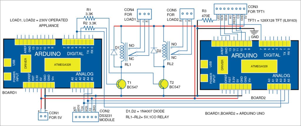
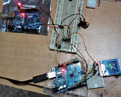
TFT ILI9163 is an 128×128 dots colour display that runs on SPI bus along with Reset, AO, and CS pins that run on the second Arduino. When the GPIO pin fires on the first Arduino (Board1), the same is read by the second Arduino (Board2) on pin A3 using digitalRead (relay) to trigger the relay on/relay off display.


Schematic
Digital pins 3 and 4 act as relay control pins from the first Arduino while the A3 pin on the second Arduino reads this status to process inside the second Arduino. TFT ILI9163 is connected on the second Arduino to display time. The RTC DS3231 is shared by both these Arduinos. The relays (RL1 and RL2) connection go further to the contactors for switching off the AC, which needs to handle bigger load.
Depending on the triggering action in the program, both relays RL1 and RL2 will be energised or deenergised simultaneously.
Following relay on/off time formats are used in the source code:
//—– Enter on times ———-
int on_hour[]={12,12,12, 12,12,12, 12,12,12 };
int on_min[] ={15,17,19, 22,23,25, 27,29,31 };
int on_sec[] ={15,15,15, 15,15,15, 15,15, 15};
//—– Enter off times ———-
int off_hour[]={12,12,12, 12,12,12, 12,12,12 };
int off_min[] ={16,18,20, 22,24,26, 28,30,32 };
int off_sec[] ={15,15,15, 15,15, 15, 15,15, 15 };
Accordingly, relays (RL1 and RL2) will be either on or off. In the above example, relays on time in the first case is 12 hours, 15 minutes and 15 seconds. Similarly, relays off time in the first case is at 12 hours, 16 minutes and 15 seconds. These on/off timings can be changed in the code as per your requirement but with the same format as shown above.You can see each of this on/off time of the relays on the TFT display along with real-time clock (date and time.)
There are two source codes for this project. First code is DS3231_AC_Scheduler.ino for Board1 and second is DS3231_AC_Scheduler_Display.ino for Board2. First source code is used to set the timings to control the relays at specific time through Board1. The second source code is used to display the time, date, and status of relays on TFT display through Board2. Before compiling and uploading the source codes to respective Arduino boards, you need to include the related libraries such as RtcDS3231.h, TFT_ILI9163C.h and Adafruit_GFX.h in Arduino IDE.
Bill of Materials Cost
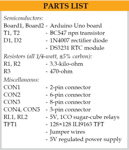
1 DS3231 ($1)
2 ATMEGA328/UNO ($4)
1 128×128 TFT [ILI9163] ($3.5)
2 5V sugar-cube relays ($1.5)
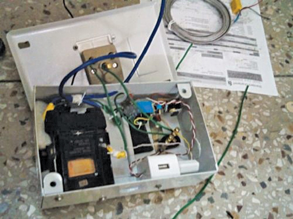
The total bill of materials cost comes to about $10 or about ` 750, excluding the box, contactor, and 5V power supply.

Aftermath
More circuit ideas on dual sharing of RTC are possible, including in a stroboscope where one microcontroller will create the variable pulse while the other will display the pulse frequency and rotation of shaft, while both the microcontrollers share one RTC.
Somnath Bera is an avid user of open source software. Professionally, he is a thermal power expert and works as additional general manager.


