 This design idea outlines a method to use an analogue switch and discrete components to reduce the power dissipated in relay actuation. Presented here is an MAX4624-based circuit to drive a 5V relay in a more efficient way.
Relays are often used as electrically-controlled switches. Unlike transistors, their switch contacts are electrically isolated from the control input. On the other hand, the power dissipation in a relay coil may be too much for battery-operated applications. You can lower this dissipation by adding an analogue switch that allows the relay to operate at a lower voltage.
Circuit and working
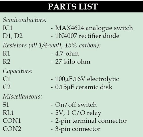
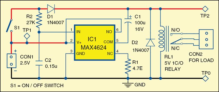
Fig. 1 shows circuit diagram of the efficient 5V relay driver. The circuit is built around 1Ω, low-voltage, single-supply SPDT (single-pole, double-throw) analogue switch MAX4624 (IC1).

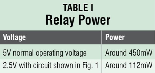
Power consumed by the relay coil equals V2/RCOIL. The circuit lowers this dissipation (after actuation) by applying less than the normal operating voltage of 5V. Note that the voltage required to turn a relay on (pick-up voltage) is greater than that required to keep it on (dropout voltage). The relay normally has a 3.5V pick-up voltage and a 1.5V dropout voltage, yet the circuit allows it to operate from an intermediate supply voltage of 2.5V. Table I compares the relay’s power dissipation with fixed operating voltages across it, and with the Fig. 1 circuit in place.
 When you close switch S1, current flows in the relay coil and capacitors C1 and C2 begin to charge. The relay remains inactive because the supply voltage is less than its pick-up voltage. The RC time constants are such that C1 charges almost completely before the voltage across C2 reaches the logic threshold of the analogue switch. When C2 reaches that threshold, IC1 connects C1 in series with the 2.5V supply and relay coil. This action turns on the relay by boosting the voltage across its coil to around 5V (twice the supply voltage).

As C1 discharges through the coil, the coil voltage drops back to 2.5V minus the drop across D1, but the relay remains on because that voltage is above the relay’s dropout voltage (1.5V). Component values for this circuit depend on the relay characteristics and the supply voltage. The value of R1, which protects the analogue switch from the initial current surge through C1, should be sufficiently small to allow C1 to charge rapidly, but large enough to prevent the surge current from exceeding the peak current specified for the analogue switch.
The value of C1 depends on the relay characteristics and on the difference between input voltage and the relay’s pick-up voltage. Relays that need more turn-on energy require larger C1 values. The values for R2 and C2 are selected to allow C1 to charge almost completely before C2’s voltage reaches the logic threshold of the analogue switch.
Construction and testing
An actual-size, single-side PCB for efficient 5V relay-driver is shown in Fig. 2 and its component layout in Fig. 3. After assembling the circuit on PCB, enclose it in a suitable plastic box.
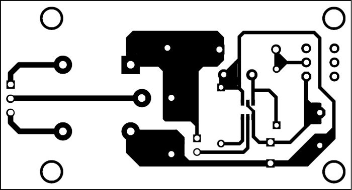
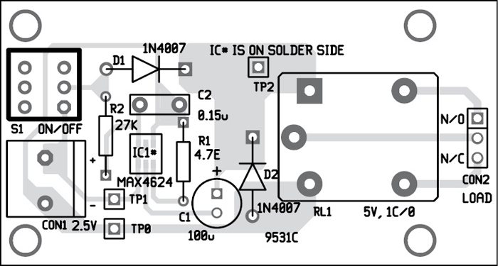
Download PCB and component layout PDFs: click here
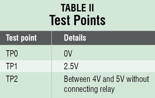
Before connecting the load, verify that the voltages at various points are as per Table II.
The circuit is based on Maxim application notes.