 The circuit presented here can be used as a lock for important electronic/electrical appliances.
When card is inserted inside its mechanism, depending upon the position of punched hole on the card, a particular appliance would be switched on.

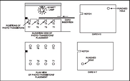
The card is inserted just like a floppy disk inside the disk drive. This card should be rectangular in shape with only one punched hole on it.
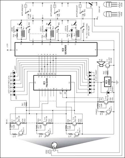
The circuit uses eight photo-transistors (T1 through T8). When there is no card in the lock, light from incandescent lamp L1 (40-watt, 230V) falls on all the photo- transistor detectors. Transistor T8 is used as enable detector for IC1 (74LS244). When light is incident on it, it conducts and its collector voltage goes low. This makes transistor T16 to cut-off, and its collector voltage goes high. This logic high on its collector terminal will inhibit IC1 as long as light is present on phototransistor T8.
IC1 will get enabled only when the card is completely inserted inside the lock mechanism. This arrangement ensures that only the selected appliance is switched on and prevents false operation of the system.
You can make these cards using a black, opaque plastic sheet. A small rectangular notch is made on this card to indicate proper direction for insertion of the card. If an attempt is made to insert the card wrongly, it will not go completely inside the mechanism and the system will not be enabled.
When card for any appliance (say appliance 1) is completely inserted in the mechanism, the light will fall only on photo-transistor T1. So only T1 will be on and other photo-transistors will be in off state. When transistor T1 is on, its collector voltage falls, making transistor T9 to cut-off. As a result, collector voltage of transistor T9 as also pin 2 of IC1 go logic high. This causes pin 18 (output Q1) also to go high, switching LED1 on. Simultaneously, output Q1 is connected to pin 1 of IC2 (ULN2003) for driving the relay corresponding to appliance 1. Similarly, if card for appliance 2 is inserted, only output pin 16 (Q2) of IC1 will go highmaking LED2 on while at the same time energising relay for appliance 2 via ULN2003. The same is true for other cases/appliances also. The time during which card is present inside the mechanism, the system generates musical tone. This is achieved with the help of diodes D1 through D7 which provide a wired-OR connection at their common-cathode junction. When any of the outputs of IC1 is logic high, the commoncathode junction of diodes D1 through D7 also goes logic high, enabling IC3 (UM66) to generate a musical tone.
In this circuit IC1 (74LS244) is used as buffer with Schmitt trigger. All out puts ( Q1 through Q7 ) of this IC are connected to IC2 ( ULN2003) which is used as relay driver.IC2 consists of seven high current relay driver. IC2 consists of seven high current relay drivers having intergal diodes. External free- wheeling diodes are therefore not required.
When an input of this IC is made logic high, the corresponding output will go logic low and relay connected to that pin gets energised. This switches on a specific appliance and the corresponding LED.
Once a specific card is inserted to switch on a specific relay, that relay gets latched through its second pair of contacts. Thus even when the card is removed, the specific appliance remainson. The same holds true for all other relays/ appliances as well. The only way to deenergise a latched relay after removal of the corresponding card is to switch off the corresponding switch (S1 through S7) which would cut-off the supply to the desired relay.
The +5V and +12V supplies can be obtained with conventional arrangement using a step-down transformer followed by rectifier, filter and regulator (using 7805 and 7812 etc).


